
Build Tips
Under Hood Cosmetics
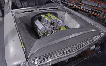
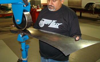
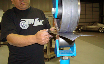
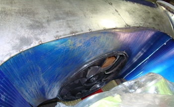
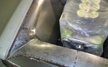
The finished product in bare steel. A sight to behold or was that a sight to Behemoth!
The first step in building a one of a kind engine bay is making sure that all the front end sheet metal fits exact, including the gaps between the doors and fenders, hood to fenders and the height of each panel to one another. If you build the engine bay metal to fit dead on like our example then it will not be adjustable later. If you change the fit of the outer body panels after the engine bay is done it will then affect how the engine bay metal fits. Be sure you have it where you want it in the beginning.
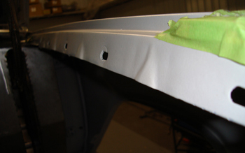
Starting with the fender you can see that our project has ribs built in to the fender flange. These will be removed to allow the new side panels to sit flat and tight against the fender.
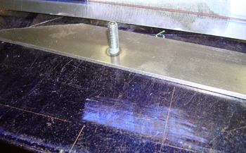
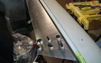
Using 1/8th thick strap steel we drilled and attached 5/16th bolts every 8 inches the length of each fender. We then tack welded them on the back side.
The strap was previously cut to match the shape of the inside fenders.
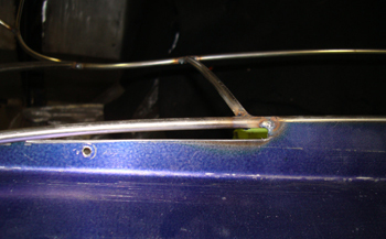
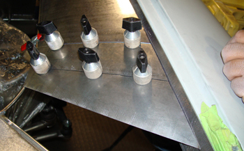
This close up on the end shows the last bolt was raised higher then the rest. The fender goes to a point at the very front so we compensated for the bolt to be centered where it goes through the fender. The top one shows the bolt head was welded and ground smooth for no interference.
Installed on to the fender you can see a washer was placed between each stud to act as a shim. This will allow some body smoothing filler work yet still allow clearance when finished.
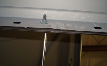
The underside shows the stud bolted to the fender. No fasteners are visible on the engine bay side with this technique.
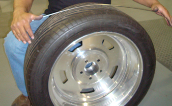
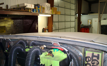
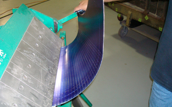
It is time to choose a design on how we want the engine bay covers to look. Letting everything flow smoothly while complimenting the engine and outer fender sheet metal at the same time is what we are after. We did some initial drawings and are ready to build. Louie uses a high tech tool, a " rubber tire" to bend the rods for his basic shape.
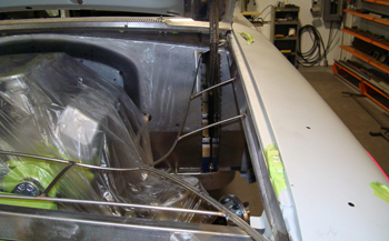
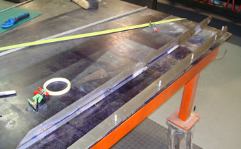
We chose a tapered design that starts at the back fire wall and gradually swoops around toward the engine as it makes its way to the front.
This angle shows the wire making a smooth transition up and over the radiator as close as possible. Avoiding hood clearance issues and still making it serviceable for removal is crucial.
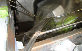
The double wire is where the panels will be eventually separated to allow servicing.
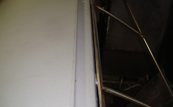
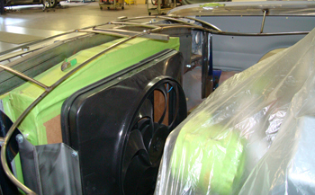
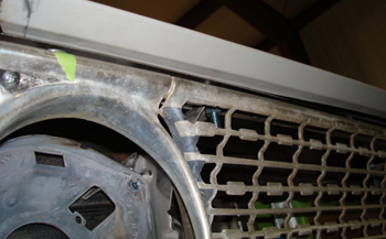
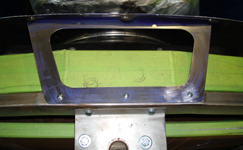
Once we laid the wire forms out with our basic shape we formed the front panel above the head lights with some simple flat panels. This allowed a close fit to the edge of the grille clearing all the hood striker parts while allowing easy visual entry in to the engine bay as it gently angles up and over the radiator support and on to the fan covered panel. Check out the copper coated 1/8th wire tacked on for a mock up transition to the fender edge.
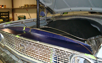
With the hood closed we still have ample room at the edge of our grille.
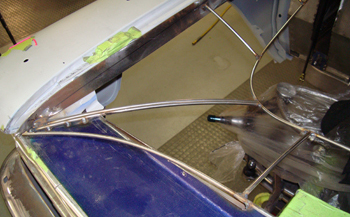
The top and side panels all meet at the same points for a nice transition.
We cut a relief on the headlight cover to clear our new 3/16th wire where we had the copper coated one mocked up earlier.
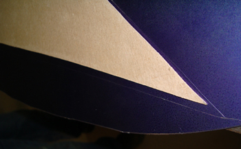
A small slice of metal will fill this corner up with a soft transition.
Louie cut the piece out and is ready to attach it.
Tacked in she is starting to take shape and looking good.
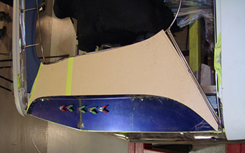
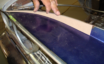
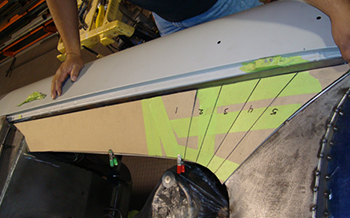
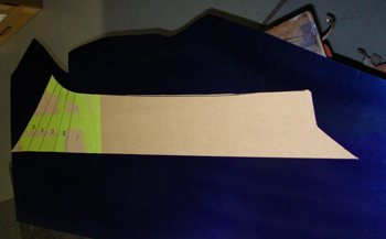
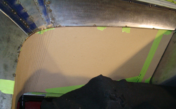
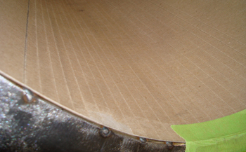
Next is the top radiator panel which we cut out in card board to get an idea of the size and angles needed.
She looks awesome so Lou is cutting out some 20 gauge with the electric shear to match the template.
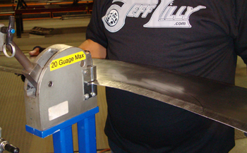
He runs it through the Mittler power shrinker to put a crown on the panel. A little bit around the entire perimeter and it is starting to take shape.
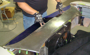
Louie checks for initial fit and likes what he sees, I bit of wheeling to level out the panel and he will be happy.
The English wheel removes all the little highs and lows made by the power shrinker.
Another fit and he is pleased so time to tack weld in place
The side pieces require a more intricate mock up as they have a wild shape to connect them from the back to the front. Separate pieces need to be made in order to make it happen.
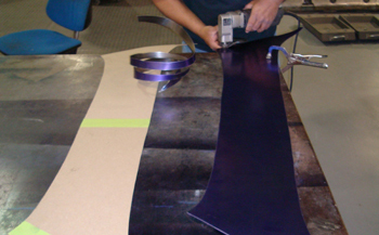
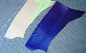
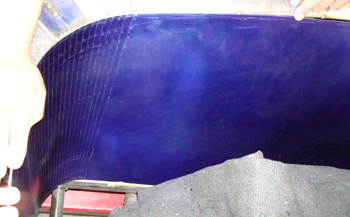
We use blue lay out dye for precise scribe lines on sheet steel.
Laid out and ready to cut some metal.
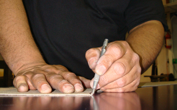
Once the dykem blue is dry the scribe line leaves a nice scribe line that is easy to see which aides in cutting it out.
As seen the line is precise and allows great visual for precise cutting.
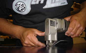
Using an electric nibbler he cuts real close to the line then uses an angle grinder to fine tune the edge.
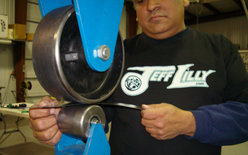
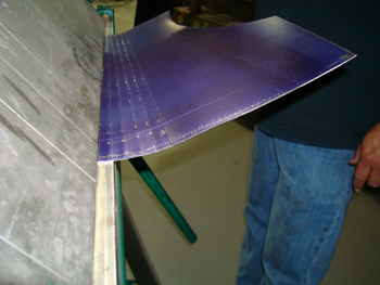
Note the rubber wheel on the large steel roller. This allows aggressive stretching to make maximum time. Lou puts a bit of crown on the long rear portion of the cover.
Using the planishing hammer is is able fine tune the panel to his liking.
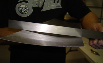
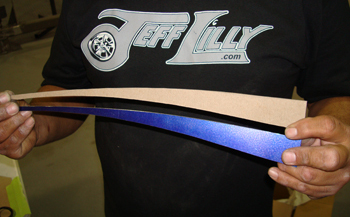
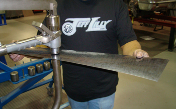
The straight edge shows just how much concave shape we put in to this panel.
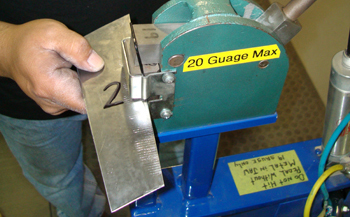
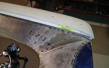
Starting with the # 2 piece we shrank it to fit in to the confines allowing each one to blend together forming a free flowing panel.
Again, as with the other section we needed some wheeling to level it out and get it ready for fitting.
The longer rear section fits well and the small sections are coming along.
Using panel clamps keeps them level with one another to enable perfect welding.
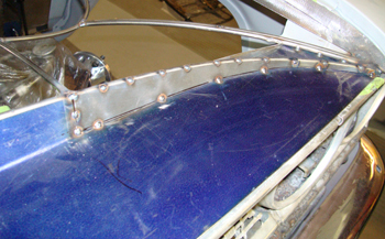
The same procedures were carried out for all the individual pieces. We then tack welded them in to place.
Next we mock up the inner apron which sits below the side covers and keeps the debris from the tires being thrown onto the engine.
Notice the lines formed by the brake tool. This is the same technique we will use on the steel. Little increments at the right angle can bend metal very subtle with very little distortion on the panel.
Laid out, cut and then we scribed the increments where the brake will form the side panel. We are ready to bend some steel.
The idea is to insert slightly to each line then bend just a bit then move on to the next line and do the same.
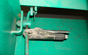
Using a pair of vise grips Luie has a built in stop to do the same bend each time.
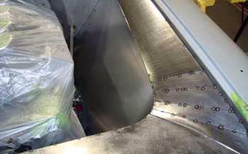
At the end you can see the curve gradually made in to the panel. Lets check for fit.
Fits dead on the first time. Because of the mock up we knew exactly how to proceed.
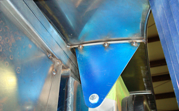
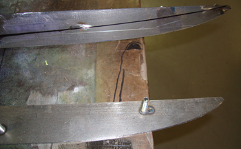
On the radiator cover we fabbed a small angle bracket to attach on the underside. Removing the front tire allows easy access to this bolt.
We also fabbed the radiator / fan cover much in the same way.
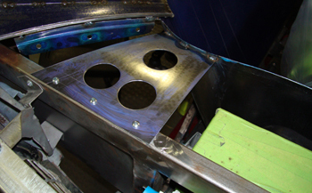
We built some supports to hold the fan cover on. This is directly under the radiator cover.
Center brackets supports the radiator cover also.
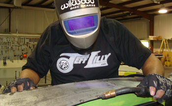
Looking good and ready for final welding.
Style looks great and once painted she will be one of a kind.