Seat Belt Retractor
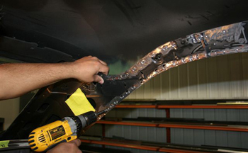
We start off by drilling out welds and removing a section of the interior roof panel that supports the headliner bows.
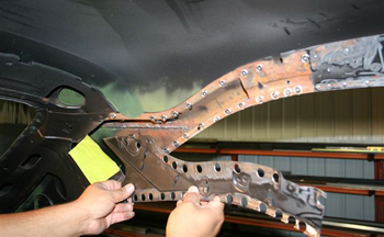
Pulling back the panel we can see that there is ample room to install the Custom belt track guide and the re-tractor box we are building.
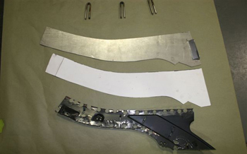
Using the original roof panel as a template we made a paper board mock up and cut out new metal to build our guide system.
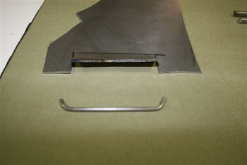
On the wide end of our guide panel we cut and turned up the metal to allow the seat belt to move freely near the retractor. This will assure that no binding takes place. Luie fabricated a wire to weld on to the end so the belt will slide easily past the entrance.
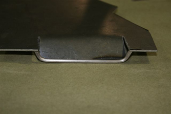
Wire welded in place the guide is starting to take place.
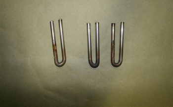
Luie fabricated small u-shaped guides out of 1/4 inch stainless rod and will polished them up in the inside to allow the belt to track smoothly without hesitation.
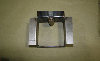
The seat belt retractor box was built to install in to the roof pillar, a double long nut was welded in place to attach the belt retractor and allow for change out if ever needed.
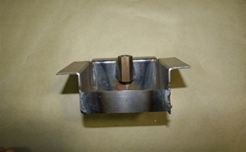
Another view shows the retractor box as it will sit in the pillar. Once fitted and every thing working properly this will be welded in the roof permanently.
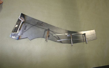
The u-shaped guides are welded in place at specific angles to allow the belt to run in a natural arc for this particular roof. This is important so that the retractor not only pulls out smoothly but will also wind back up easily.
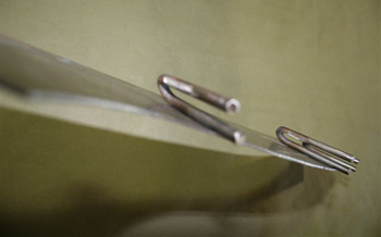
Another view shows the u-guides welded in. Note the different angles they were placed in.
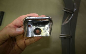
This is the seat buckle bezel. It was fabricated from 1/4 stainless rod and 16 gauge flat sheet. As seen a countersunk screw will be used to hold it in place. This along with all the visible parts will be Black chromed to blend in to the black headliner.
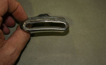
Another angle shows the small arc. This was designed to match the natural arc/curve that the headliner has. This insures that every thing will flow properly and look good to the eye.
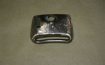
We flip it over and you can see the locator pin welded on the back side to keep it from swiveling once installed
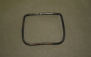
This ring fits the outside of the bezel made from 1/8th rod. It will get welded in just around the perimeter of the bezel. It will be used to help support the headliner which will be wrapped then glued around it.
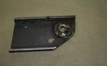
This support bracket holds the bezel in place and welds to the roof pillar.
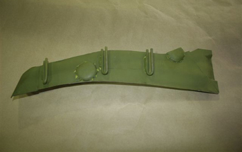
Welded up and primed on the back side the guide plate is ready to install.
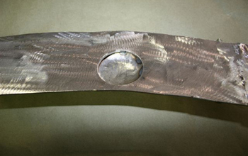
We turned the guide plate over and you can see where we attached some recessed cups. These are for the headliner bows to clear when reinstalled in to the outer panel we removed in the first photo. The outer panel has the holes that accept the headliner bows and will be put back on in the end.
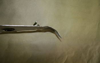
This angle shows the extension at the end of the guide plate. As seen it curves out to match the bezel and the headliner
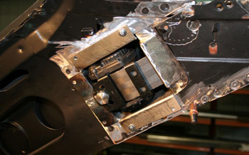
All the parts have been fabricated so we are now installing them in to the roof. We start with the retractor box and belt assembly installed.
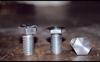
The bolts to hold the retractor in to the box were shaved a bit on the head to allow for the roof pillar panel to have additional clearance.
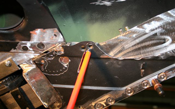
Part of the original roof panel with the headliner holes was put back in the factory location.
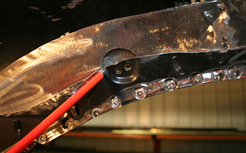
The original panel lines up with our recessed section on the guide plate allowing the headliner bows to go back in the factory location.
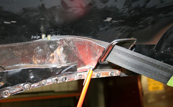
The belt pulls out very smoothly and retracts just as nice!
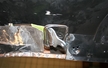
Close up of the bezel plate installed shows the belt latch up tight but out enough to grab a hold of. This system allows the occupant to have a chest restraint in a custom car with out the seat belt hanging down from the roof which is unsightly.
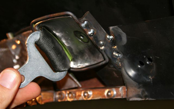
Simply reach back over your head and two finger grab, pull out, click in to the catch and your ready to drive away.
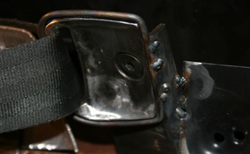
This close up of the bezel ring shows the 1/8th clearance around the bezel. The headliner materials will be wrapped tightly around this and glued in place as discussed in caption 14.
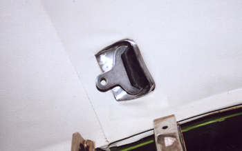
We did a quick mock up on the passenger side of the old headliner to show what it will look like. This particular project will have a black headliner so the black chromed bezel and belt tongue will blend in nicely.
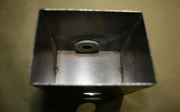
This is part 2 of the floor retractors. We left off with the shoulder restraint section hidden in the roof. We are on to the floor retractors which are also hidden and sunk in to the floor. This outer floor retractor will be installed floor level just to the outside of the bucket seat by the step plate.
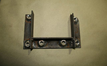
The floor box top bracket will be welded to the box once the box is in place. This piece has 3/8 nuts to secure the box to the floor with 6 bolts to be super secure.
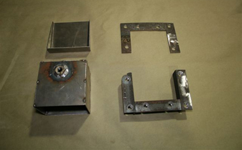
All four pieces are ready to install.
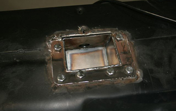
We have the top plate bolted in for mock up. The bolts will be countersunk during final assembly so that the carpet will lay flat in keeping with the step plate.
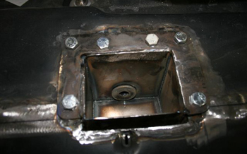
A close up shot shows the washers welded in at the bottom of the box for extra strength where the retractor will be bolted in.
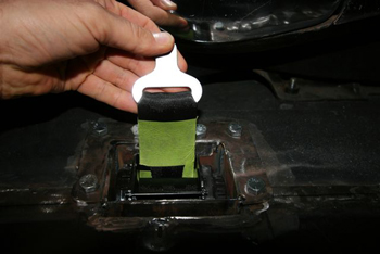
The retractor is installed and works great. We will build a trim bezel to cover up the retractor/belt on top of the carpet. The bezel and belt tongue we are holding will then be plated black chrome when we are finished.
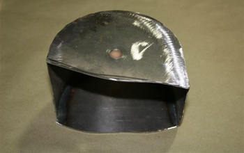
This is the side cup for the inside retractor assembly which will house the belt coupler section, it will be welded in the floor to support the unit next to the console between the seat.
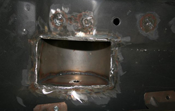
We have welded it in place and it is ready for the retractor to be installed.
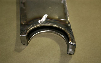
This is the top section of the retractor belt/coupler holder. As seen the cradle will support the round coupler when not in use.
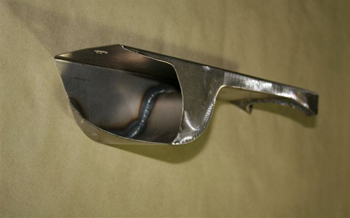
The bottom view shows a cut out section which allows the system to swivel some to enable even contact with the occupants stomach regardless of their height and bucket seat adjustment.
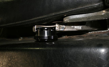
Bolted in place it fits great. The round buckle coupler will also be plated in black chrome before final install.
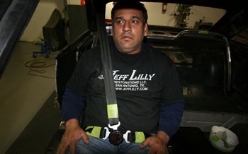
Louie puts it on and it fits good. It is extremely important to be supported between the neck and shoulder dead center for driving comfort and maximum accident protection.
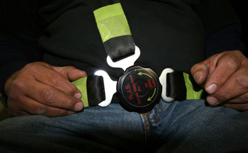
Simply twist the coupler and they release simultaneously.
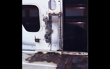
In many of our projects, customers want chest restraint seat belts installed. We often build enclosures inside the A and B pillars down in the inside rockers to mount the retractors. This is done to hide the balky retraction units as well as keep the passengers from tripping on them in 2 door vehicles. On this particular project we fabricated inner wells from 18 gauge steel to surround the units and keep them clean.
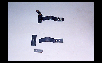
When we build restraints for our customers their lives depend on our craftsmanship! Check out the support brackets "Overkill" to the max made from 1/4 inch plate steel to fit inside tight areas while being removable if need be.
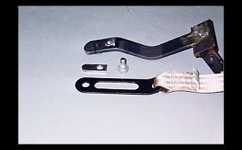
The lap belt attaching strap must be secure as well as pivot front to back for optimum support and fit to any occupants body size.
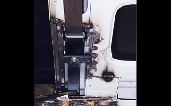
As shown we have installed the retractor with support brackets. In addition check out the custom stainless roll guide which keeps the belt from twisting while moving in and out during use. Many of the factory MFG belts get twisted because they do not spend the engineering money to attach a guide such as this. We build components to work effectively in all areas.
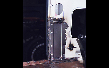
We have attached the center cover which separates the inside retractor or chest restraint portion from the pivot and / or lap portion of the restraint.
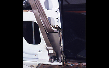
For visual purposes the outer cover is attached to show how it will separate the inside belt from the outer belt to keep them from ever conflicting with one another.
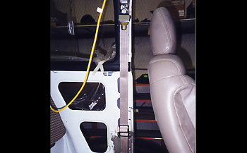
As seen the seat is installed to show the clearance as this is a 51 Ford Woody 2 door. Keep in mind that this is how the occupants will enter the rear seat. Our new belt system goes back tight against the B-Pillar to avoid a rear passengers foot from being caught during entry and exiting. This system is well thought out and ready to perform.
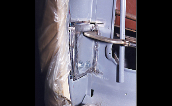
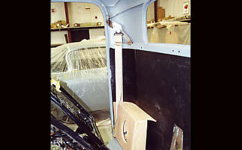
Another look on the outside qter panel where the wood will cover, shows an area we needed to add a box to clear some of our retractor mechanisms.
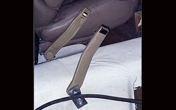
We go on to the inside buckle as this also needs to be placed correctly alongside the seat.
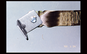
A close up shows the slot we cut into the belt mounting bracket above the nut. We inserted a roll pin in to the bracket which stops the coupler or buckle from flopping forward or back too much. It will pivot in a 30 degree arc which makes it fit small, medium and large occupants.
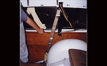
Off to the rear seat belt system. We have flipped the seat down to show the location. We anchored it to the floor and we are now going to pre fit for the owners torso and waist size.
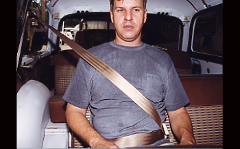
Jack shows the belt is fitting decent but is a bit low on the shoulder bone. We will raise the mount a bit to get the belt to fit an inch higher toward his neck or just above the shoulder bone.
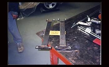
A close up of our rear seat upper chest restraint bracket shows 1/4 inch plate which will bolt up to the roof rail and just below the sliding window.
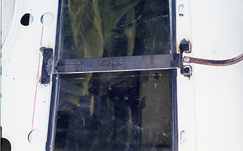
We used countersunk screws to attach the brackets. Sturdy and ready to support for maximum safety.
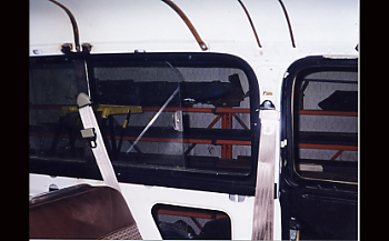
We used countersunk screws to attach the brackets. Sturdy and ready to support for maximum safety.
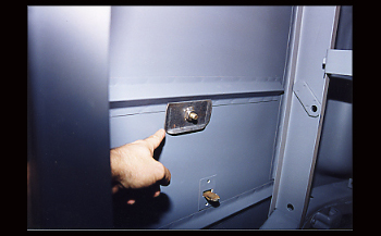
This is our bottom side bracket mounted to the underside floor which supports the lap portion of the belt.
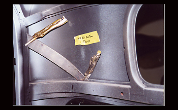
Due to limited space we cannot show every belt system we have fabricated but here is a few more to give you the basic idea. We can Fabricate restraint systems to fit many makes and models.
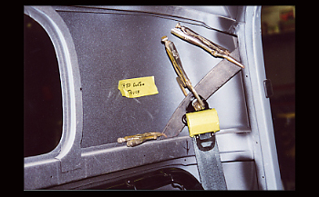
50 Truck shows angled upper cab mounts which allows us to make changes to fit the owners specific size.
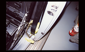
Often we mount the bottom retractor straight down from the upper pivot because we will hide the unit in a speaker box assembly as we will show you next.
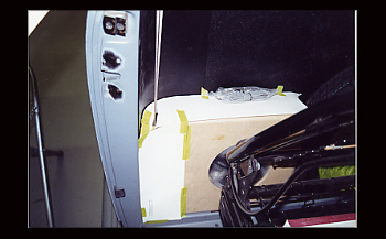
We have mocked up the side of the speaker box to cover the retractor assembly while making the speaker box fit smoothly in to the back of the cab.
Seat Belt Retractor

