Build Tips
Nascar Sway Bar
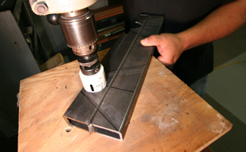
Mounting a Nascar Sway-bar requires heavy duty mounting pads. Louie starts out with using 1x2 tubing 1/8th thickness and tack welds two pieces together. He then marks them with the correct angle to match the frame. Using a two inch hole saw he cut through the tubing for a bushing to be mounted.
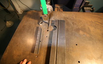
Lou marked the center line of the tubing and sliced it for two halves.
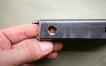
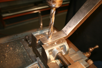
He flipped the tubing over and drilled two 7/16ths holes allowing 3/16th of an inch beyond the bushing /saddle hole. Close enough for maximum strength yet far enough for mounting bolt clearance.
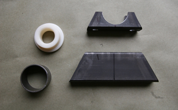
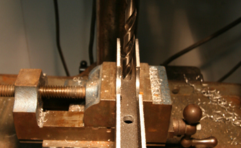
We matched the holes on the bottom/larger section which will be the mounting pad. This will be welded solid to the frame. Note the center line mark for reference to assure all the holes are dead on when drilling. A nylon bushing with matching tube sleeve will be used to keep the sway-bar in precise alignment.
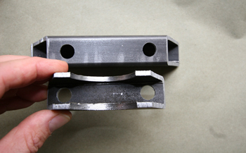
A close up view shows the pieces trimmed on the band saw and ready for some assembly and welding.
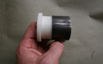
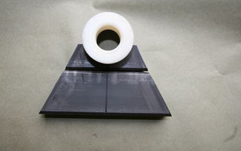
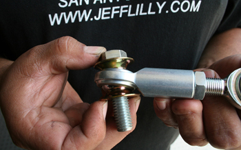
The tube sleeve and nylon bushing will allow a pressed fit for the sway-bar shaft.
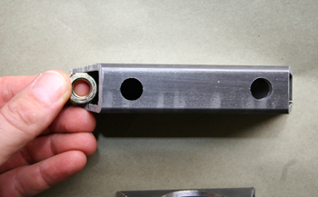
Now we will install 7/16th nuts to the inside, A bit of shaving was needed to slide them inside the tubing.
Once in place you can see they fit well, We will now weld them in place to elimanate the need to use a wrench when tightening the bar to the pad. We simply used a bolt and tightened them down before welding.
You can see the mount coming together and taking shape.
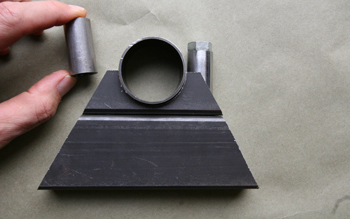
The bushing/sleeve is placed on to the saddle and all fits well. Next we cut some small round tubing to fit the 7/16 grade eight bolts we will be using and placed them next to the bushing sleeve to check for clearance. It is time to weld up our unit. To hold it all in place we drilled a hole in to the sleeve to allow tightening of an allen head set screw in to a bushing collar /retainer we will also be installing.
We pressed in the nylon bushing and slid the retaining collar over the shaft. This will keep the sway-bar from walking left to right in the bushing during hard use and is a necessary safety measure.
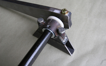
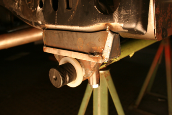
A close up shows the unit in its completed state ready to be mounted and tested.
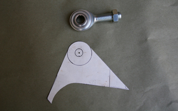
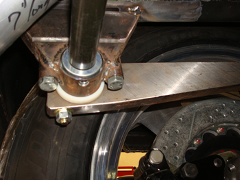
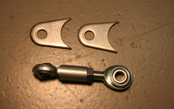
We paper mocked a mounting tab/bracket which will allow the heavy duty rod end to mount to the 9 inch Ford rear end.
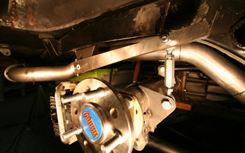
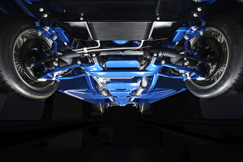
As seen during our initial fit there is ample clearance between the rear tire and exhaust.
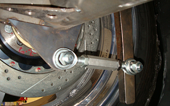
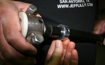
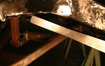
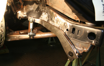
A close up of the rod end shows plenty of clearance on the back half of the rear end.
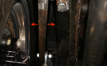
Having even clearance between the tire and frame rail which is important.
This side angle shows the retainer in place, note the ample exhaust clearance
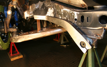
On the front sway-bar mount we built it with a riser to clear our frame and core support. We brought it down 2.5 inches. We fabbed the removable bar mount the same as the rear.
As seen the sway-bar ends will hit the frame so they will need to be bent. Cold bending is best so off to the handy bender we go.
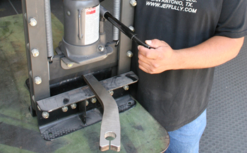
Louie marked his spot and is ready to bend the end. A 25 ton press is needed to move a piece of steel this thick.
It now has a nice kick and clears the frame just enough with 3/8ths of an inch clearance.
We marked and drilled the bar for the rod end link to attach.
Small mounting tabs were fabbed to hold it all steady and fit the lower control arm.
Special rod end bushings are used to allow greater movement.
Mounted and ready for some hard cornering