Hidden Hinge
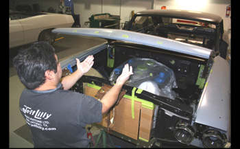
As seen Nat Ramirez lifts the hood up 4 inches and the smooth action Gas Shocks take over to bring it to the upright position.
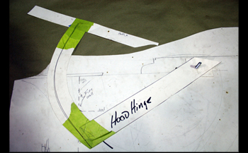
Louie mocked up the hood hinge rotation in correlation to the firewall to allow enough clearance when the hood was being raised. Another factor was to be sure the arc that we needed would not change the hood to cowl cover panel clearance. On the interior side of the cowl and floor area we needed adequate room to install the Gas Shocks toward the outside of the car. This way the slightly angled kick panels to be built will look natural with out closing down the floor space width for the occupant’s feet. On the driver side the emergency brake foot pedal system will be changed to a pull up unit.
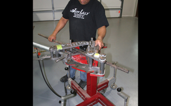
We chose 1 inch chrome-moly tubing for light weight as well as overall size so the hinge would look trick but subtle when finished. Louie set up the Model 6 bender and bent two equal left and right side pieces with 110 degrees of arc. Tools like this are time efficient but a home shop can get the same results by simply filling the tubing with sand and then torch heating it to bend over a round surface if need be.
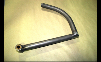
The basic hinge welded and ready to fit. As seen we cut a straight length determined for our application and pie cut both the bent section and straight piece then welded them together while clamped. The bushing ends are one inch long. The straight tubing section was hole sawed with our joint jigger tool on the drill press using a bi-metal 1 inch cutter. We then welded it all in place.
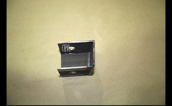
The pivot box bracket was fabbed using 1/8th thick angle iron. This part will be bolted up in and against the drain cowl which we will show you later.
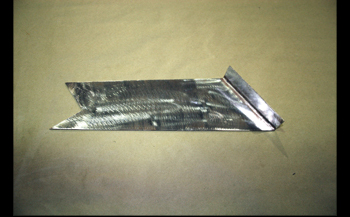
This pivot box support strap bracket was fabbed from 14 gauge steel. We simply paper board mocked it to attach to one side of the pivot bracket down to the firewall to provide front to back support for the hinge.
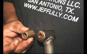
On the pivot end of the hinge Louie installed a bronze bushing that matched the inside wall of the tubing with a press fit.
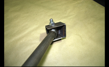
The pivot box was previously drilled to match the bushings inside diameter and we inserted the correct bolt to match for a snug fit.
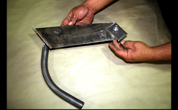
We installed our pivot support plate and then welded it around the outer perimeter of the box. We are now ready to trial fit to the cowl.

On the firewall Louie marked off the approximent area the hinge will be inserted through the firewall with enough clearance to accommodate a full swing of the hinge.
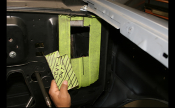
Using a cut off wheel he sliced on the line and removed the old firewall metal on both sides and it is ready to trial fit.

As seen the pivot bracket goes up inside the cowl where the original air vents were located. Note the hole on top of the pivot bracket. This was drilled then a nut was welded up inside the pivot box. This will be used to bolt the assembly to the top of the drain cowl.
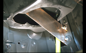
We needed more clearance for our hinge to make a full swing so Louie cut out more of the original drain cowl side wall. If your cowl is like this style you will need to build a wall around ¾ inches tall in the section you needed to cut out to keep any water from coming in to your interior. This is important if you get caught in a rain storm or are spraying in to your cowl vents during washing. On our project we do not need to add a wall because we are closing off the vents on top of the cowl given it is an A/C car and we do not need outside air thus eliminating any leaks.
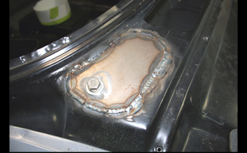
This shot shows where we reinforced the top of the drain cowl where the hinge pivot box was bolted in place. Be sure you have ample clearance between the bolt head and the drain cowl cover.
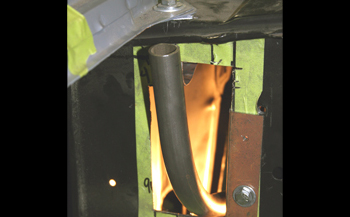
The hinge clears the firewall fine. Later on we will build a nylon brush cover to keep dust and debris out of the interior but still allow the hinge free unrestricted movement. Once the inner fender aprons are fabricated this part of the hinge will be covered and viewable only from under the front fender.
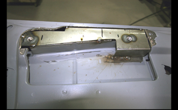
We flipped the hood over to get it ready for attaching to the new hinge system. As seen we welded in a new hinge bolt plate with a longer pattern then the factory did. This will allow a nice transition from the mounting bolts to the gradual radius of the hinge which we will show later on.
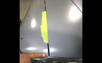
We laid the hood down in place with shims to get our 3/16th gaps along with our hood and fender edges being level. Now we will check to see where the new hood hinge makes contact.
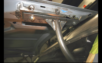
The hood hinge was shaved to make a nice contact with the hinge plate and then tack welded on. We lifted the hood up and down and all clearances were dead on. We then welded some gussets from the hinge to the flange plate to beef up the system for no flexing. Strength is first and beauty will come later.
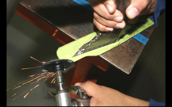
The hood lifts up and down smoothly so we removed the hinge from the pivot bracket and ground down the mounting plate edges to a shape that matches the outer edges of the hood for a nice transition.
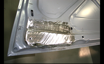
We were happy with the fit so we flipped the hood back over and Louie boxed in the factory hinge pockets for a smoother look.

Beauty time! We fabbed some metal covers for a smooth and subtle transition of the custom hinges. We then tack welded them on for now and will finish welding them before prime and paint as the project progresses. You can see them starting to take on their character.
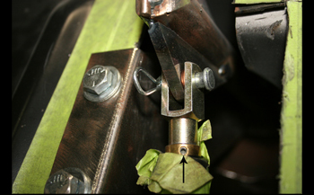
We go on in to the interior side and show you a small triangular bracket welded to the very end of the hinge where we originally pie cut the straight section with the bent section as seen in Cap 3. We welded this on and our adjustable gas shock is attached with a clevis rod and quick release pin. Take a look at the black arrow pointing to the Allen head set screw. This allows gas to be released from the unit which changes the amount of tension going down. Turning the set screw out just a bit then back in we released a little bit of gas till we have the right amount of closing pressure.
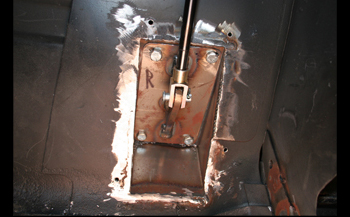
As seen in this floor shot Louie built a box to attach the bottom of the gas shocks with a clevis. This is fabricated a little more stout from 12 gauge, most of the force is on the bottom of the shock so it needs to be stable. A custom fabbed angle kick panel will be built to easily remove for service if ever needed while looking good to the eye next to the carpeted floor.
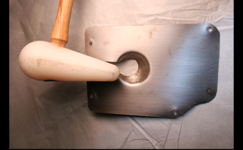
Using 20 gauge sheet he took two blocks of wood and paddle drill to make a 1 and 1/8th inch hole in to make a sandwich. He then took a plastic mallet and formed a cup to clear the pivot at the bottom location.
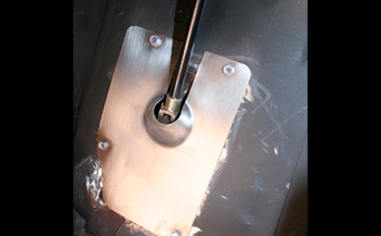
Installed it fits nicely and finishes off the floor section.
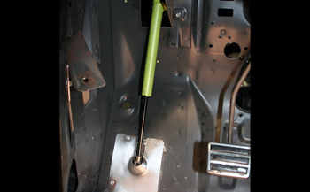
A full shot shows a clean install with plenty of foot room and brake pedal clearance. Once the angled kick panels are installed she will look great.

