

Build Tips
Header Fabrication
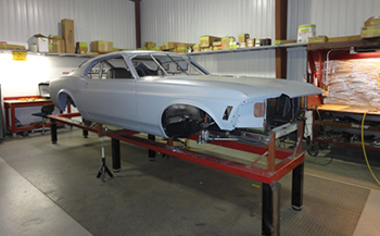
Our candidate for a custom one off set of headers is a 1970 Mustang. This car will feature an all aluminum 351 W putting out 750 HP and backed by a 4 speed 480LE GM automatic transmission. The custom Ford 9 inch will have 35 spline floating axles. This project is from Australia so we aptly named it the "Out Back Fastback "
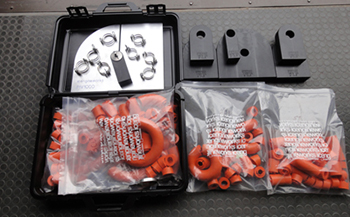
The ICE engine kit comes with all you need to build a set of beautiful one of kind headers and is available in whatever diameter pipes you need for your particular application.
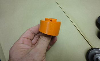
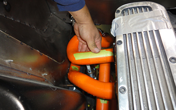
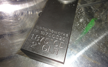
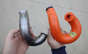
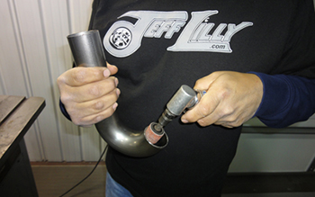
As seen the individual pieces snap together like legos with different angles to snake around components and inner fender/suspension parts. These come in 2, 3,4, and 6 inch radius pieces to make any tight or large radius.
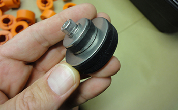
With the rubber starter modeling adapter you simply tighten to expand it in the cylinder port to hold the pieces in place
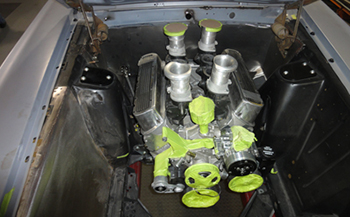
Here we go. The engine bay is stock with the mock up 351 alloy sitting in position and ready to flow some serious exhaust.
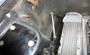
As seen this particular project is being converted to a right hand drive for an Australian client so the steering shaft is very angled with some borgeson joints. This is one of the main reasons a custom exhaust is needed.
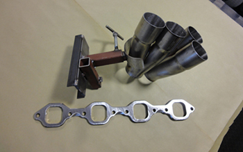
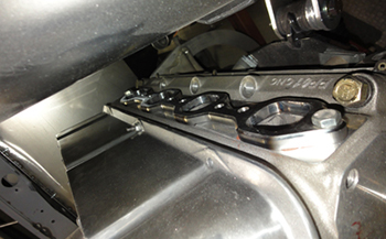
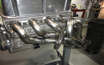
Over the years we have built a few jigs that keep everything aligned and the Y-collector is our first positioning part. The goal with the collectors is to position them so they give the best clearance while allowing maximum space for the 3 inch tubing coming off of it. In our particular application we are building a Tri Y design which incorporates a step header system. We start with 1 3/4 tubing for 10 inches then 1 7/8 from there on down to the Y-collector. This is the ultimate for maximum horsepower and torque. As seen our square port flange will get bolted up to the heads to start the process.
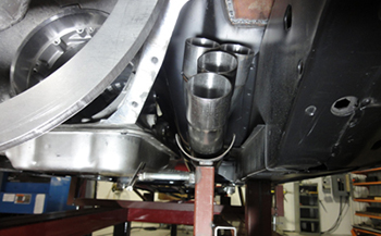
Our jig holds up the Y-collector with the proper clearance and angle for best flow. Plenty of space in and around the trans and frame rail is best but not always available in some situations. That is why having jigs to hold items in place is best. We actually start with the tube and cylinder that will be the farthest away meaning distance and or tube length as this will dictate what the minimum length will have to be for each of the other tubes. After that one is mocked we proceed to make the other three the same distance by manipulating the tubes with different turns and angles to try and match the same length as our first.
We have the flange bolted to the cylinder head and we are ready to go.
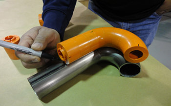
We have square ports and there is very limited space so we opted to fabricate his own, so we will start with the expandable modeling adapters and then form our square starter tubes from tight radius tubing to match our square ports. We also chose 2 inch radius blocks to get the tubes as tight to the block as possible. We attach one piece on to the next twisting and turning until we get our proper shape. They are all made in one inch increments so you can count the pieces to know you have equal length tubes for each cylinder.
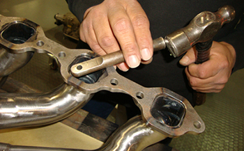
All tubing comes round so we built a forming tool that allows us to reshape the tube ends to fit our square ports. A few lite hammer taps and she will match the flange dead on. When you have tight spaces like our project it forces you to make your own starter tubes from tight radius tubing.
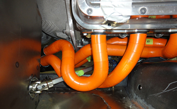
Once all the pieces have been added and clearance is optimum we can go on to building the headers in steel.
In case the mock ups will be sitting in your shop for a while until you can get your tubing it may be a good idea to place tape on the tubes to be sure no movement will take place. You can also super glue them together for permanent molds when you will be using them to duplicate many sets like in a race team situation.
As seen we taped a 1/2 spacer in place on the steering shaft to rotate it 360 degrees to be sure clearance was optimum.
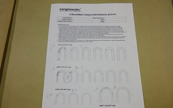
The supplied control sheet allows you to compare the individual pieces used in your mock up so you can order the correct amount of bends and tubing to build the pipes. It is a thorough check list for professionals and or a novice to be successful.
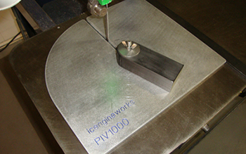
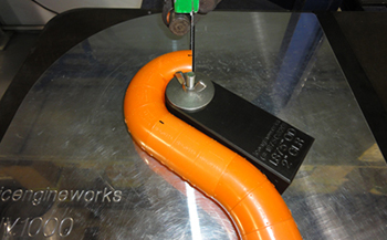
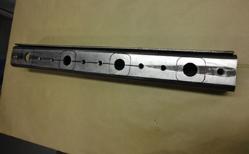
The PIV 1000 cutting plate allows you to place the forming blocks in the exact location for square cuts.
As seen we are using the 2 inch block. Each angle block is marked clearly to allow easy comparison with sizes to achieve dead on precise cuts per our mockup.
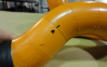
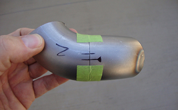
The modeling blocks have little arrows and reference bumps to show you the turns and angles in order to achieve the same results on your metal tubes. We marked one black for you to see what we are discussing. In order to achieve a duplicate part simply match the model to your cut tubing and mark it at the same reference bump or arrow and " voila " you have a match.
Simply place the correct block that matches the mockup and line up the band saw to cut precise.
After we cut the end on the matching radius we lay the mockup on top of the tube and mark accordingly.
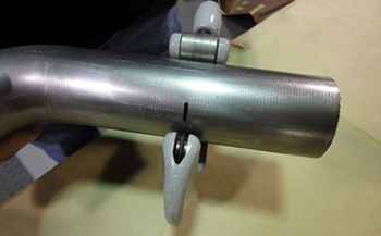
We use a tubing cutter to score the metal which provides us with a nice precise line on the tubing. This way there is no mistake when cutting on the band saw.
As seen no one could over look the line which allows a perfect eyes view during the cutting process.
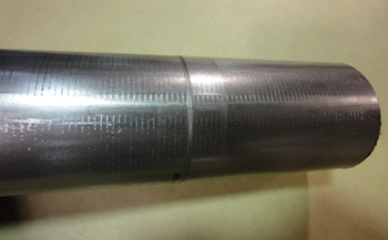
After cutting some pieces to match our mock up we tack welded a few of them and we have an exact duplicate. No tubing gets final welded until it is fit in the car and matches our mock up perfectly. As seen the #10 shows where our first 10 inches of 1- 3/4 tube ends. At that point we will start the 1- 7/8 for our hipo step up design.
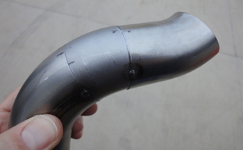
As seen this is what you want, all tubes fitting exact, three tack welds is adequate.
Once we get the pieces cut we always deburr the inside as this provides the best possible fit. Remember this above all things in the world of fabrication.
" Good Fit, Good Welds, Bad Fit, Bad Welds " !
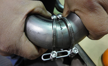
Using the ICE tube clamp it keeps the individual pieces together for hands free tack welding.
Sometimes the tubing clamps will not fit around a tighter bend as well as we would like so we simply use 3M masking tape and tack in between. This tape method is not strong enough to hold the headers in place on the car like the ICE engine work clamps but it can save a bit of time.
As per the mock up we pull the engine, then bolt the headers up to the heads which keeps them in the properly held configuration. The starter tubes remain tack welded only to the flanges while we weld up as many tubes as we can. We thene cut the starter tube tacks so we can finish the back sides of any tubes we needed to get access to. Then they are put back in place, tacked where they final fit and then removed again to permanently weld the starter tube ends to the flanges for one piece headers.
Another one of the things we like to do is tack weld a brace between the left and right header Y collector tubes to stabilize the headers at the very end while we weld the tubes.
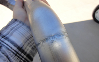
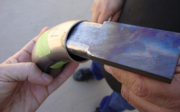
A sample weld shows what we are after. Flat and pretty. This way if you coat them they look nice and if you want to grind them it is an easy job for that mandrel bend look. Tig welding is best for the finest welds. We use ER309L stainless to carbon welding rod for best results.
Once we have welded around the tubes as much as we can we remove the headers and bolt them to a jig that matches the flange. This allows us to get better access around the back of each tube to complete the welds.
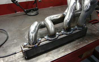
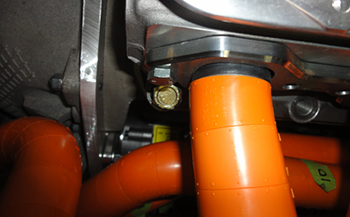
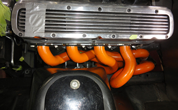
Bolted in place she is looking good. The customer opted to have each tube ground smooth as seen with no welds showing except the step up flange where we go from 1 3/4 to 1 7/8. Note the purge tube on the end which allows argon to fill up each tube for optimum welding quality.
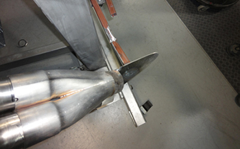
A simple drift is used to lightly tapp the square formed tubing tightly to the square flange ports to get it ready to weld on the inside.