

Build Tips
Fuel Brake Lines
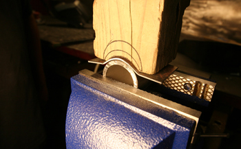
We start off by fabricating saddle brackets to mount our fuel pump. We simply used a piece of tubing the same size as the fuel pump housing, Using a hole saw we cut out a section on a block of wood then sandwiched some 18 gauge metal between the pipe and wood forming block and gave it a few taps.
As seen it forms the part very precisely and takes little time to make. Luie then marked it and bent the ends to the correct angle on the Tennsmith brake.
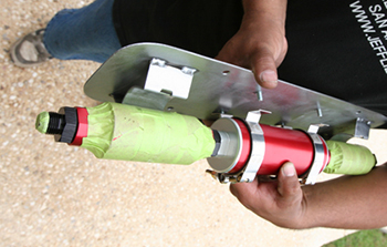
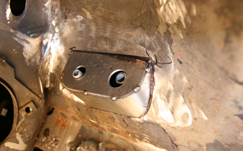
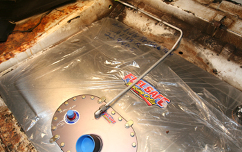
We then welded the custom built saddles to a 14 gauge mounting plate with rounded corners. We also attached studs to the mounting plate to allow the Aeromotive fuel pump brackets to hold it in place.
We chose to mount the pump and bracket assembly to the 4 link system we installed in to the car earlier. This location is centered in the car and close to the fuel cell providing the optimum location.
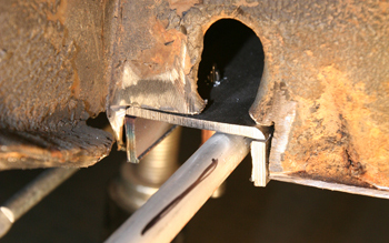
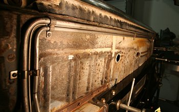
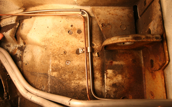
We are keeping the original floor in this Cougar so we will work around the original metal Ford installed. As seen here at the edge of the torque box we cut a section out where we could run a U-channel up against the floor allowing the line to be flush with the remaining floor which not only looks better but keeps it from getting damaged if a floor jack or rock and debris make contact in the area.
We made the U-Channel wide enough to accommodate the fuel and brake lines in the pocket as seen from the side view here.
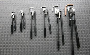
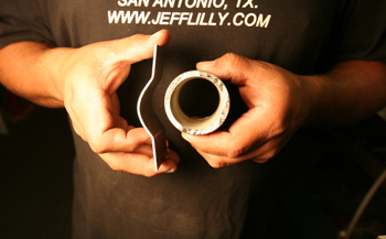
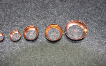
When bending lines with the correct radius you need to have good quality benders. As seen we have actual samples of 90's we bent next to them. We recommend that you bend some 90's with what you have. Benders can vary in the actual radius they will bend so by coming up with an actual sample of each size you will then use this to mark the tubing in the exact location for a superior fit.
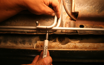
As seen in this picture the straight tubing needs to be bent to go inside the line that is already in place. We simply laid our template bend with the matching O.D. up against the line and marked where we will place the line in to our bender. This allows exact no guess bending.
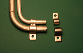
At this time no one makes double clamps with different sizes on the same clamp. We take Kugel clamps and cut the end off the smaller one and weld them together. When running fuel injection systems such as our project you will need a return line that is smaller in diameter so be prepared for such sizing and clamp fabs.
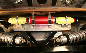
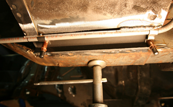
Once installed and fitted to the car you want your lines fitting and running true as seen.
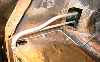
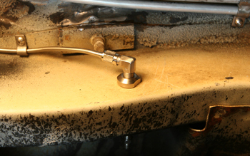
At the channel we fabbed earlier "black arrow" we needed to bend the lines up at a tight 90 degree bend to come up through the fender apron and mount to a bulk head fitting. We made a joggle bend to give the proper separation for the hoses and their fittings to clear one another.
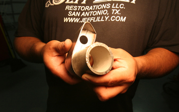
Luie used another piece of tubing sized to his specs and wrapped a piece of 18 gauge steel around the pipe, he then welded a flat base pad to it to form a mounting base for his bulk head fittings.
This view shows it tacked in place and roughed out.
Another technique in figuring bends in lines is to mock up the bends you want in 1/8th rod as seen."red arrow" This allows you to see the layout on multiple bends before you bend the actual tubing to be sure you are satisfied with the look and fit you want.
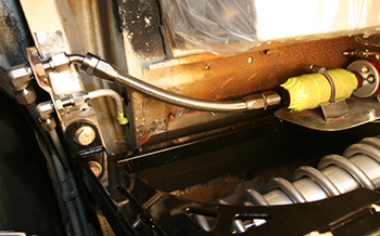
At the rear we snaked the lines around the original uni-body and built a bracket with a Z shape to hold the fittings in place. The "red arrow" shows the Z bracket. In order to get a small fitting and large fitting to clear each other in a limited space this is often necessary. We then attached a stainless flex hose to the pump.
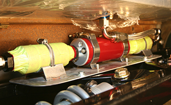
We also used a stainless flex line from the fuel cell to the fuel pump to pull the fuel and send it on its way.
Up top in the trunk we bent and installed the vent line to the fuel cell.
When going through frames there are different sized "thru frame fittings" available from Godmans. Simply measure your frame width and order accordingly.
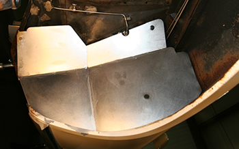
As seen we built a splash to protect the lines from tire debris with only the disc brake hard line showing.
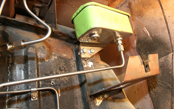
A view of the hydraulic throw out bearing reservoir hidden up under the fender shows there is still room to allow access to service the unit. Fluid is not changed very often so this is not a problem.
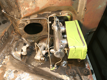
We come back in to the engine bay and take a look at the master cyl #1, just below is the slave cyl for the throw out bearing #2 and the fuel line bulk head fitting mount pad #3
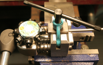
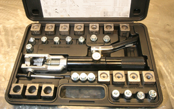
This is where things get a bit tricky as proper flares for sealing are a must, We use this unit from East wood # 25304 which allows multiple size flares to be done. It has a rotating head for quick change of flare sizes and will do 3/16, 1/4, 5/16, 3/8 and 4.75mm including 45 degree double flares.
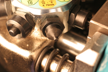
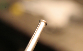
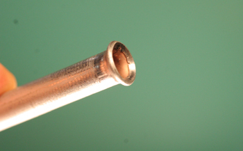
A close up shows the double flare we will be using on our project.
It makes a Double Flare very crisp and clean
We also use this Imperial unit for AN lines when performing 37 degree flares. This is used most often when doing stainless brake lines. It features a roller tip that does not mar the surface.
It performs a nice flare with no marring on stainless.
Once installed the stainless ferrule fits precisely.
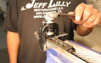
This # 11535 hydraulic flare tool from East wood works especially nice when you have a line fitted on the car and you need to flare it without removing all the holding clamps and taking the line to a bench unit. It will form a perfect flare on the vehicle.
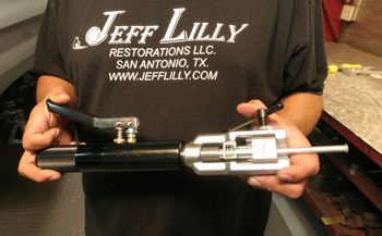
It is slender and can go right up against the body panels in tight confines. It performs many different flares including 3/16 to 1/2 double flares. 45 degree double flares, push connect flares, GM fuel line, metric bubble flares etc.
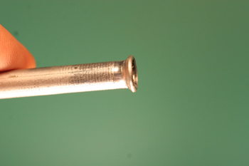
This close up shows a nice double flare.
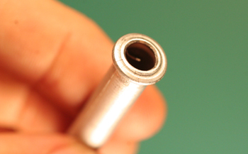
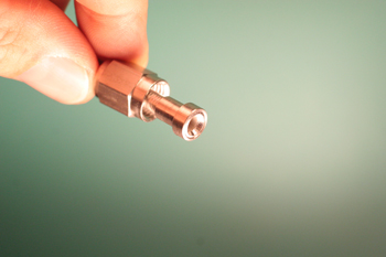
Metric bubble flares, no problem.
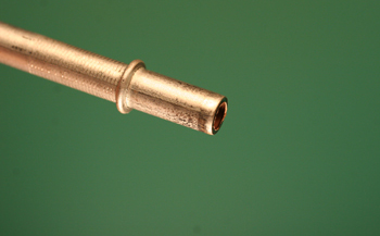
Push connect flares for vac hoses etc are all done.
These tiny copper gaskets go in between the fittings and flare for that extra margin of sealing. When doing stainless lines this is where they shine as you do not have to tweak the line wrench so hard to get a proper seal.
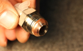
Once tight they conform with the soft copper for an exact no leak fit.
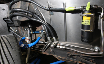
Different types of line materials are used during the plumbing of a Super Rod. Rubber lines can be used in high heat low pressure such as water/coolant and also come in high pressure materials for Freon applications. As seen around the shock - spring tower rubber lines can be clamped tighter to a body panel surface compared to other materials such as hard lines in stainless/aluminum and stainless flex lines, In this particular application these lines were chosen because of the tight confines. Once covered by a trim panel they will go undetected
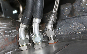
Up inside the engine bay bulk head fittings were placed for the best hose route and smoothest look possible. Water, Freon, power steering etc