
Build Tips
Camaro Front Wire #2
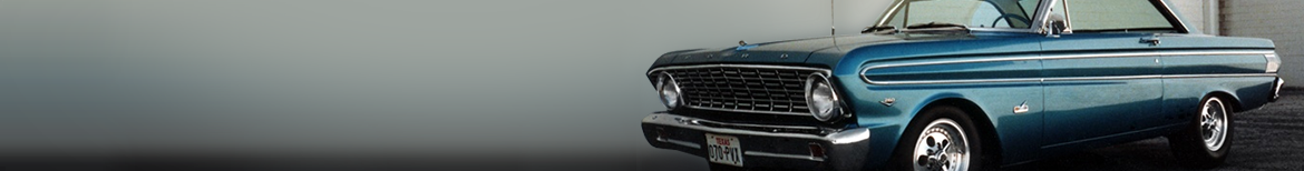
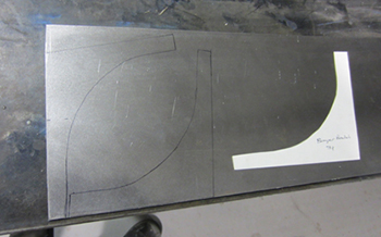
First things first, we need our grille opening dimensions to be exact side to side. The outsides of the opening are nearly impossible to hand bend the 1/4 inch wire precisely so Bob makes a forming plate out of 3/16th steel to match our chip board mock up. He then drilled some holes to clamp the wire in place.
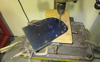
As seen our forming plate matches our chip board mock up exact.
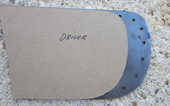
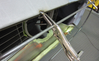
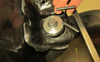
Needle nose vise grips are used to hold it in place as he heats the wire and forms it around the opening.
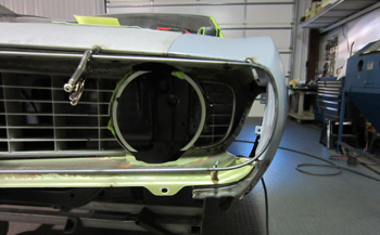
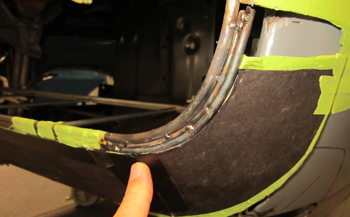
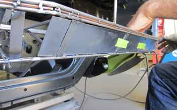
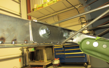
After the wire was fabbed he placed it in the same location as per my mockup dimensions.
He cut some short 1/4 inch wire to fit in the confines and then clamped them in place before tack welding them. These will stabilize the outer wire and keep everything held in place as we lay out the forming wires.
Side view shows how it is parallel to the original G. M. fender and header panel but slightly lower as it flows downward.
Bob ran some tape for a visual to be sure all was in order. We quick marked a transition line at the top for another perspective.
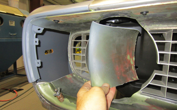
He cut out the old plastic grille sections on both sides to allow room for the new 1/8th transition wires.
As seen the new transition is more subtle and the wires stop at about the one inch mark from the outer edge of the sealed beam compared to straight back like the original which was 3 inches away from the sealed beam.
A paper mock up shows the new transition we decided on at the top of the fender to cover the extension.
We formed these wires to give us a transitional guide line of how it will flow from the outer fenders edge down to the center of the fender. It is a difference of 1/4 of an inch in height.
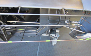
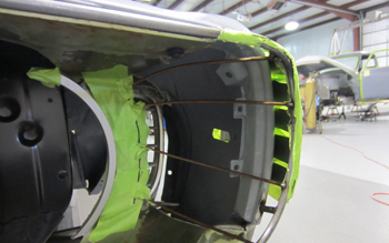
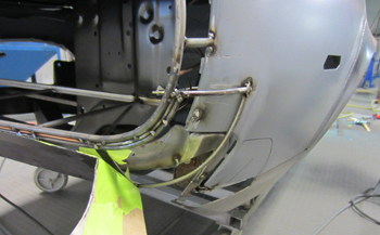
Bob then ran the front and back wires of the grille opening including the bottom support system.
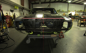
This aerial view shows the reduced size opening well. If it was left unchanged the header panel would be too long front to back because of extending the front end. To eliminate this problem we will be extending the hood to make the header even shorter then it was from the factory. The longer hood will allow us more room to tweak the cowl section.
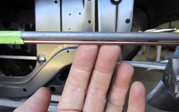
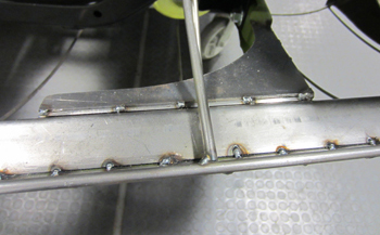
Next on the list He started adding the 1/8th wire below the grille opening which sets the gap between the bumper.
It goes all the way around the outer curved areas. Eventually this 1/8th wire will be cut away to leave a precise 1/8th gap between the grille opening and the top of the bumper. It currently acts as a shim between the main panel wires.
Now that he has them set in place it is easy to see the lay out. The upper 1/4 wire will be the outer edge of the lower grille opening surround. The 1/8th is a shim wire that will eventually be removed and the upper bumper edge was formed in 3/16th wire.
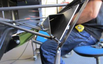
He peels the mock chip board bumper away and as seen he has the lower bumper wire installed in 3/16th also.
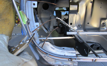
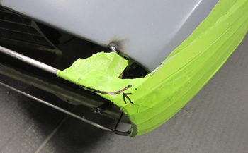
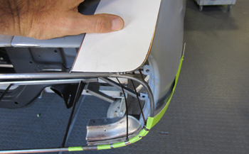
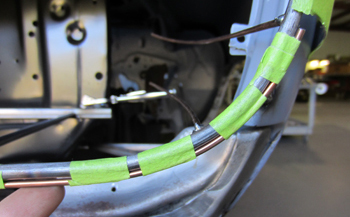
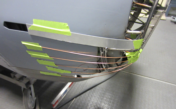
An area of great importance is shown on the passenger side bumper end. Making the transition up the side of the grille surround Bob slowly turns the 1/8th gap and 3/16th bumper wires inward so the bumper will flow perfectly in to the side of the fender. This has to be very subtle and is tricky to do but worth the effort.
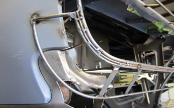
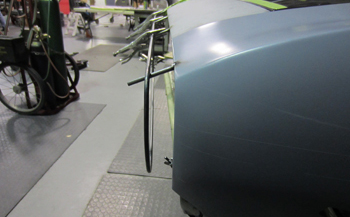
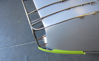
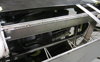
Side view shows the bumpers outer wire form in place. A few 20 gauge flat steel braces were placed in the center to support it as it was being fabbed.
We then placed some full length 20 gauge steel in between the wires to add stabilization and provide a place to mount the bumper brackets. This not only strengthens but keeps all the wires from moving when the full welding is taking place.
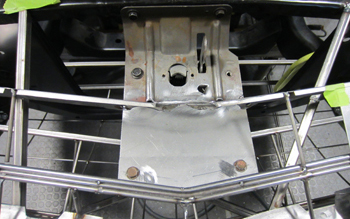
A simple 90 degree bracket was fabbed for the left and right side of the bumpers back side. These will have nuts welded to the inside section to remove the bumper brackets we will fab.
This is the original 1969 Camaro bumper bracket. We blasted, primed and bolted it up to our sub frame. Now we will build some extensions to bolt to these and our new bumper.
We drew out some new brackets on 18 gauge to fabricate from.
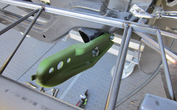
As seen the new brackets are bolted to the back of the bumper.
He then capped the brackets off for a finished look.
Time to get the center points marked where we will fit new sheet metal to. I set up the lazer and leveled it out on the body to locate the exact center and then marked it accordingly.
We lay out wire per our mock up.
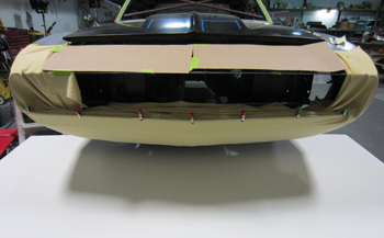
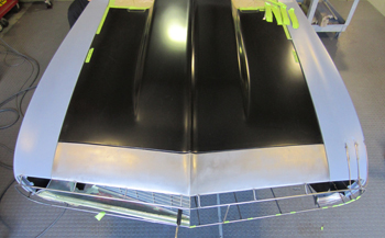
On larger panels we stretch polyester fabric around the wires and secure it with spring loaded clips. This gives us a full scale 3D look to study. As mentioned before what ever it takes to make decisions ASAP in order to save time we implement it.
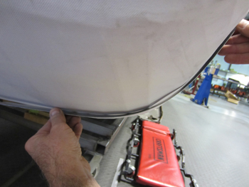
Using a flexible straight edge we bend it around the wires and see a slight dip which tells us the main wires need a bit of tweaking to get it right.
The old header panel has been removed and Bob has added a channel for strength where the new header panel will start.
We simply extended the hood striker plate right below the new location of the hood opening. I saw no reason to change the hood catch and location pin as it will have a cover around it anyways.
Once the front end sheet metal has been aligned it is vital to pin the radiator support and frame location. Bob drilled them with a 1/8th bit and has T Pins in place. This way during final reassembly everything goes back in to its original location for a Dead On fit very quickly.