Engine Bay
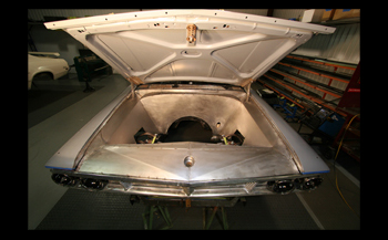
Custom Street Rods have been the trend setters for new and innovative designs and the Engine Bay is an area that has garnered much attention on Custom builds. The engine bay also supports the front end sheet metal and roof weight. Designing a new engine bay allows you to cover the unsightly area between the grille and radiator, reroute the wiring, brake lines, brake booster, battery tray and many other items to clean up your projects look. On this project we are going to build the engine bay with no exposed fasteners and all the items mentioned will be hidden.
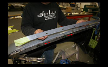
We started off by lining up the front end of the car including fenders, hood, core support and grille to the point where we had all of the gaps to our 3/16th standard and all panels were flush fit and or level with one another. Our fire wall was built before hand with 16 gauge flat sheet for structural integrity. Next we cut off the old fender lips and welded on our matching double flanges made from 1/8th thick steel. Note! The line up pins " red arrow" to allow quick attachment when final assembly takes place.
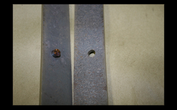
This close up shows the two flanges with the line up pin inserted. They are matching halves. As seen in caption #1 we welded one half to the fender and the other will be welded to the inner apron we will fabricate.
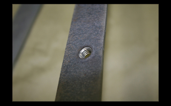
We welded 5/16 nuts on the inner apron flanges so the bolts will draw the apron in from up under the front fenders. The bolts will be very short, around 1/2 inch long so they do not hit the inner apron metal when installed.
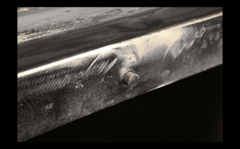
A close up shows the flange welded on and ground smooth. This is where you have to take your time and weld no more then 1/4 long beads at a time, then cool down with an air blower between rounds. This is important to keep from warping the fender
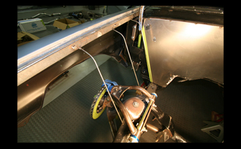
Next we bolted up the apron flange to the matching flange we just welded to the fender. We then started running our support form wires in the basic shape we want the design to be by simply tack welding them in place. We used stainless 3/16th diameter wire, as it holds its form against the panels better then regular carbon steel. Once you get your wires installed it is time to run poster board on the panels to get a 3D look to be sure you are satisfied with the design.
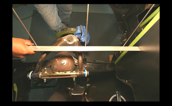
Being sure the wires are parallel to the fire wall and even we use a straight edge. This is important to lay out the apron straight and true especially matching the driver and passenger side.
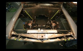
As seen we have our wire shape system laid out including the radiator/core support cover with the basic shape we like. Once you run the paper board over it to see the contours in 3D you can alter them if you want to make any changes before shaping any steel.
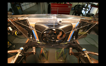
We take a look from the engines view and we laid out the wires to cover our 3300 cfm big dog fan. As seen we also lowered our custom built radiator 3 inches so the fill cap would be below the surface of our sheet metal work.
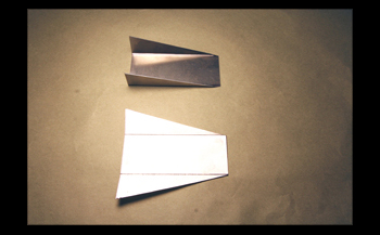
We need to be able to attach our panels with out seeing any fasteners so Luie simply bent a couple brackets to weld to the modified core support.
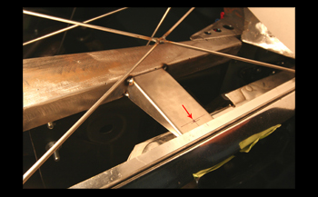
The brackets were tack welded to the core support. They will be drilled and have 10/32 nuts "see arrow" welded to secure the radiator cover.
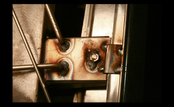
Aside from the main core support brackets we added a few smaller brackets with additional wires to the main frame to hold down the cover.
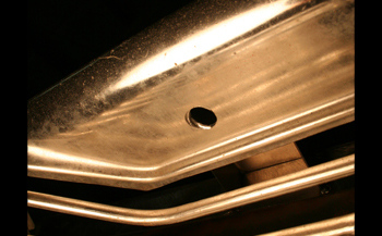
Looking up from the bumpers point of view these small 3/8 holes are drilled through the grille where no one will see them walking around the car. A 1/4 drive extension with tiny fasteners will secure the cover. In addition this area of the grille will be sprayed with satin black paint so the holes will go undetected.
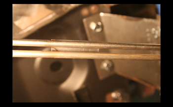
The electric fan covers need a 1/8the gap as that is where we chose to separate the upper main cover from the lower halves. We simply tack welded a piece of sheet metal to keep the spacing while we fabricate the sheet metal. Once we are done with the metal panels we will slice this back out so our panels will be independent from one another.
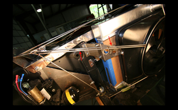
Taking a step back we can see the location "red arrow" where the space is. The other arrow points to the wire we will also be cutting to separate the panels once the metal work is done.
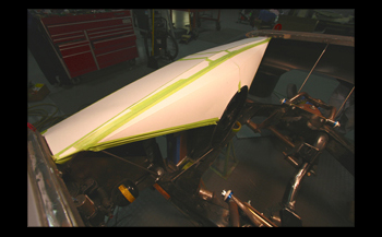
Paper board gives you an actual 3D view. Now is the time for wire changes if need be. We are happy with what we have so on to the metal work.
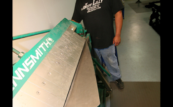
We start with our upper grille radiator cover first. This panel has multiple angles to deal with so we will make it in several sections then weld them all together. Luie laid out the templates on 18 gauge steel and cut them out. On the Tennsmith brake he makes a few bends to the upper section of the radiator cover panel and she is starting to take shape.
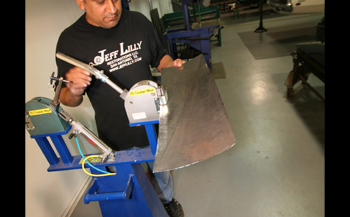
The panel needs some shrinking to get it to fit so he powers up the Mittler stretcher shrinker and tweaks it to his desires. He uses the handle on this part instead of the foot operated hydraulic system to fine touch the panel. When using a shrinker only insert the panel in 3/4 ths of the depth for best shrinking. In addition blow out the metal dust from the die teeth every so often for better grab and longer jaw life
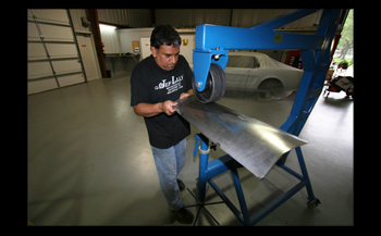
We have an unusual shape to fit. The English Wheel provides a nice affect going from sharp to contoured with a smooth transition. Note the inner tube or rubber band on the upper wheel. This allows the material to stretch to the shape you want with little or no marring of the panel and still move the metal rapidly. This is an old English or Tea and Crumpets trick.
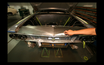
He puts it on and it needs a bit more tweaking for a perfect fit. It is headed in the right direction so he will continue with the wheeling. It is imperative to check your fit on a regular basis to be sure the tool you are using is taking you in the right direction.
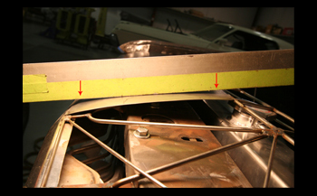
We laid a straight edge against the passenger side panel to check our contour and you can see how it slopes on both the front and rear section. "see arrows" This is the first one built so we have to match the driver side to it.
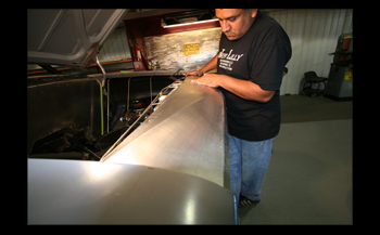
As seen the two halves mate up clean with a nice flush fit. It is time to tack weld it in place.
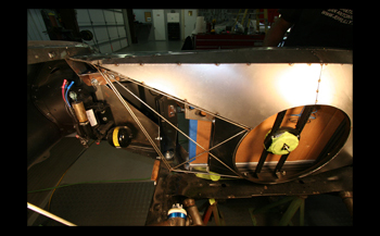
The top fan covers are done and tack welded to the upper radiator cover as one piece. These pieces were simply laid out and cut in flat sheets, then installed and tacked in. No wheeling shrinking or bending was needed. Just a bit of hand manipulation to get a slight contour. As noted in Caption # 13 we have a 1/8th gap between these panels and the lower panels that we will be building next. A1/8 th spacing is close enough to look good but large enough to enable assembly with out scratching!
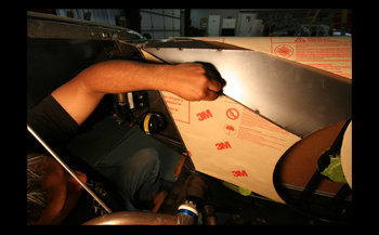
We mainly use poster board for mock ups but this adhesive heat resistant paper from 3M also works good. Luie is using a razor blade to trim off the excess against the wire frame and will peel it off to transfer it to sheet metal. Once these panels are built we will go on to the inner aprons. After all the steel panels are made we will come back to this section and cut the wires to free them from the upper section. We will then fabricate hidden attaching hardware for the panels.
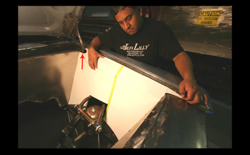
The Mock-ups are done for the inner aprons, note the "red arrow " where the oval cut out is done to clear our hood hinge. This is a critical area that we will go in to detail later.
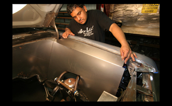
We laid out the metal from our mock up and bent it on the brake. Luie holds it in place to check the fit and she is coming together nicely. We cut just enough for clearance on the control arm to fit the panel.
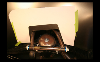
We use a template we made to cut out ample clearance for the upper control arm movement during hard cornering and bumps. Check out the custom made tubular control arms we fabbed. "Like Totally Non Geeky"
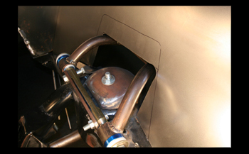
We sharpie marked the panel and are ready to cut her out.
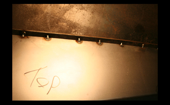
We also tack welded the inner apron at the top to our flange so we would not get any fit changes pulling the apron in and out of the car during the process.
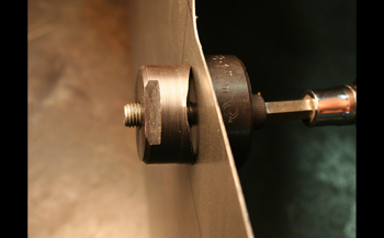
Nibblers and Air Saws can not cut a tight radius very well as in this case with the apron control arm cut outs. We usually use a hole saw as shown previously but once a panel is no longer flat it is harder to place it on the drill press so this is the best method, though a bit slower. A round die punch with the correct size pops it out with a burr free finish.
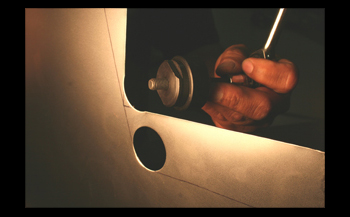
As seen she is smooth. Now we will trim it on the line with a hand shear to finish up the panel.
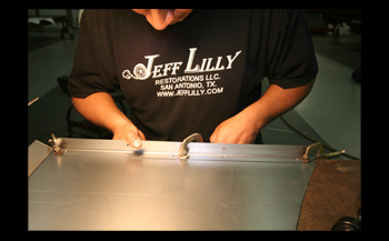
90 degree trim pieces are made to strengthen the ends of the aprons and allow attaching points for assembly. We simply drill out some spot weld holes, clamp it tight and weld it against a plane straight surface.
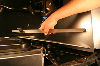
Back over to the lower, driver side fan cover, we bent a 90 degree flange to add rigidity with an ear for the cover to attach to the fiberglass fan housing. This is an aerial view.
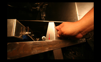
Another bracket made to attach the lower cover where it meets the upper half. As seen "red arrow" we will also add a lip to bolt this on and off to the radiator support for easy removal of the panel.
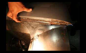
It is time for a cosmetic item to be added. This is where the radiator cover meets the inner apron. We want it to be smooth, from a transition standpoint and this looks to do the job. Tack welded only and on we go!
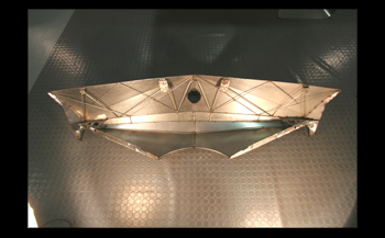
We flip the cover up side down, she looks cool with all the wire bracing and attachment points.
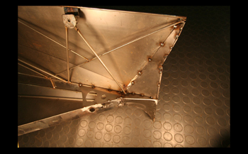
As seen she is braced up and ready for full tilt welding
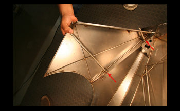
This is how the lower fan cover mates against the upper cover. A good view from the back side reveals thin wall tubing, see "red arrows" where the attaching threaded rod bolts will keep the two pieces tightly together.
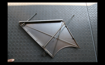
Another look with the rod bolts shows how they will be installed. A hand wrench and she is apart in no time.
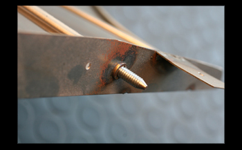
The special rod bolt protrudes through the fan trim panel. Notice the end of the threaded rod bolt. We ground it to a point to allow easy insertion in to the panel. You have to get on a creeper from under the front end to attach these.
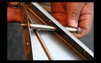
This view shows a great angle of the shorter rod bolt as it slides through its guide or sleeve tubing.
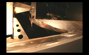
This view shows where the upper radiator cover mates against the apron, Note the contoured flange. "red arrow" There will be a fastener here also. All of the fasteners are installed from under the car and easy to get to. A smooth no fastener look is trick.
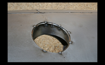
This radiused hole is where the hood striker goes inside to the catch mechanism. We simply tack welded a 1/8th stainless rod around the perimeter. When all is done we will solid weld every fabbed part.
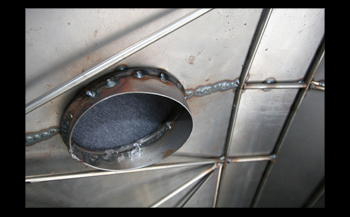
This shows the back side, A simple sheet metal ring was welded on to give a wall affect as seen in Caption 42, The bottom edge is about 1/8th inch off the top of the catch plate when you look down inside the hole.
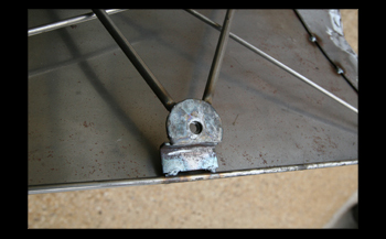
This is one of the brackets that was built to attach the cover to the radiator support. It will be fastened through the grille as seen in Caption 12.
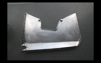
The back side of the inner apron reveals many flanges and attaching brackets in addition to the top flange.
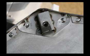
The apron attachment brackets were fabbed to fit in the bottom corners. We used simple cage nuts.
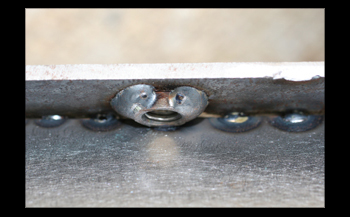
These are the small nuts welded on to the apron flange as discussed in caption #3 they are very short 1/2 long bolts so it will not hit the apron when tightened
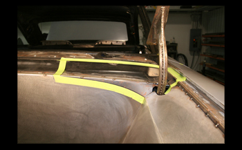
On to the cowl area we can see a major transition problem. We need to cut out a section that will allow enough room to re-shape this area to our liking. We taped it off where we feel we can accomplish the look we want, and it is time to slice.
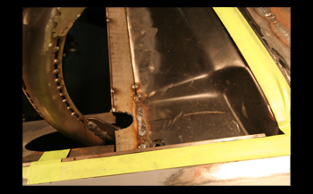
Another view from behind the hood hinge shows a pocket where the factory hood hinge went in to while the hood was down. Aside from being ugly as sin this is not needed with our new hinge style, so we will do away with all of it.
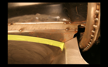
From the front side a close up shows the inner apron comes up against the fire wall with a major alignment problem. Its time to make her look good.
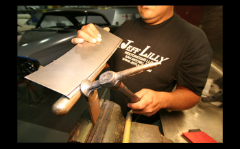
We mocked up the need panels and cut them out. Luie is using the T-Dolly to put a bead on the edge. This will match the factory cowl shape while transitional to the new pieces we are installing.
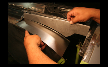
This matches the factory area with a blend to make a natural looking curve in the top of the panel. He tack welded them in and on to the next phase.
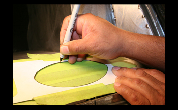
We laid out the hood hinge oval to match both sides and traced it on to tape for an exact template.
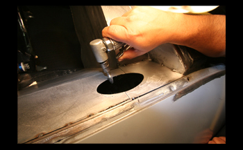
We took a hole saw to cut the ends, then roughed it out with an air saw and finalized it with a fine burr using an angle grinder.
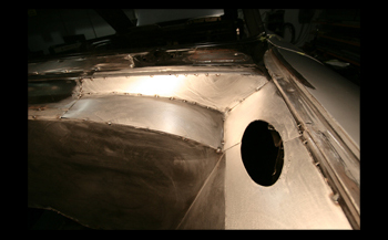
The oval cut out looks good and the transition panels blend in nice for a smooth flow to each other
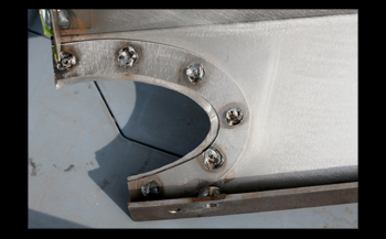
We added another layer of metal on the bottom side of the hood hinge oval cut outs to strengthen this area on both the removable apron and stationary trim piece.
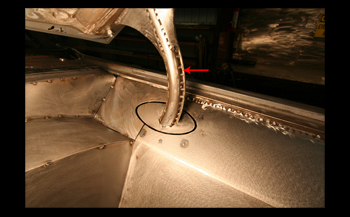
The end result looks good with the oval section attached to the hinge. A small 1/8th gap around the perimeter looks clean. The oval will simply go down and away from the apron and trim panel when the hood is lowered. The hinge itself see "red arrow" will be smoothed out with a nice taper on these wires down to the tube of the hinge.
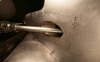
Down to the steering shaft exit we made a matching oval to allow just enough clearance and installed a surround behind it to finish it off. "sweet aye"
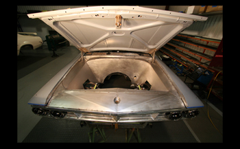
Time to step back and look at the fruits of our labor. She looks good and is ready for some primer, blocking and paint.

