

Build Tips
Custom Door
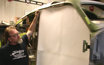
We start by making a paper board template of the door opening. We will make any adjustments needed as the door progresses.
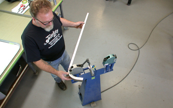
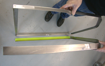
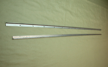
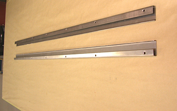
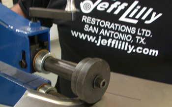
We took 18-gauge cold rolled steel and cut a 2-inch strip. We then bent it on our Tenn Smith sheet metal brake to form a 90-degree angle piece measuring 1 x 1 inch. Using our Mittler Bros Power stretcher/shrinker we fabricated the piece to fit around the confines of our template/guide and then tweaked it to perfection by fitting against the actual door opening. This is the inner section of the door perimeter.
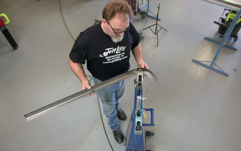
Bending another strip of sheet at a 90-degree angle to a 1 x 2 inch this time we also used the shrinker tool to form the outer perimeter of the door. Holes are punched in the inner structure along the horizontal flange for welding purposes and then the outer flange is slipped over the inner and checked for fit. This allows adjustment for the door width.
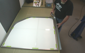
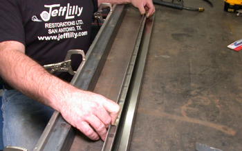
Laid out on a table we check our pieces for exact fit on our template. A little more tweaking and we are ready to rock!
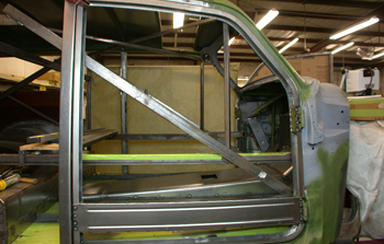
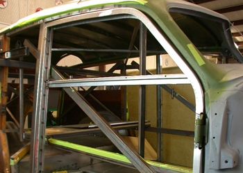
Our inner and outer pieces are starting to look like two halves do make a "Right" -- door that is! We held it up against the Woody and she looked great so on we go.
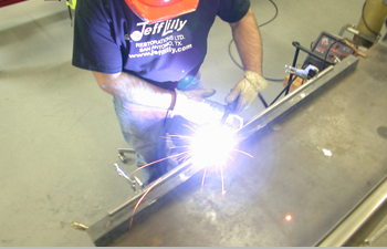
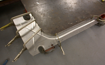
The inner and outer perimeter is now clamped together and the bottom section of the door is then welded together where the holes were punched in.
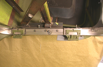
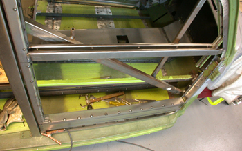
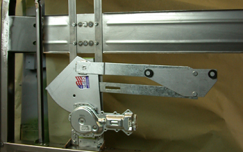
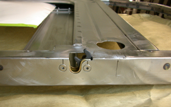
The door frame is then placed back on the car to check the fit and locate the proper hinge placement. It is then marked exactly at the hinge plate attaching points. We used the original woody hinges as they were small and in nice shape. With the wood trim installed they will be completely covered and undetected.
After we established the hinge location we used a small hole saw to drill a radius at the corners. We then use a cut off wheel and remove the remaining metal to complete the cutouts.
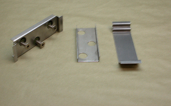
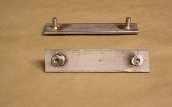
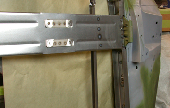
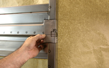
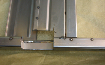
A “stair step” holder to back up the threaded fastener plate was fabricated with a front cover featuring access holes to install, remove or loosen the allen head bolts to adjust the door for precise fit.
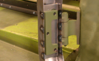
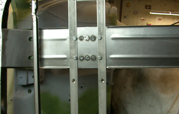
The frame is then fitted with the hinges along with the fastener plate and holder. After exact placement we welded it all in place. We now have a swinging door. Sweeeet!
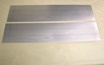
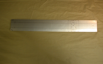
20 gauge steel is laid out for a lower support beam. We have it marked and ready to bead roll some strengthening grooves to stiffen up the door assembly.
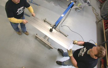
The guys roll out ½ beads on the inner and outer panel using our 36-inch bead roller. Just follow the marker lines and it is done with no warpage.
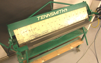
A The panels are then bent on the Tenn Smith brake to fit one inside the other. The 90 degree lips will provide the fit.
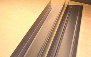
These two pieces will form the rectangular beam and will stiffen up the door nicely and allow attaching points for a power window system etc.
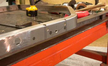
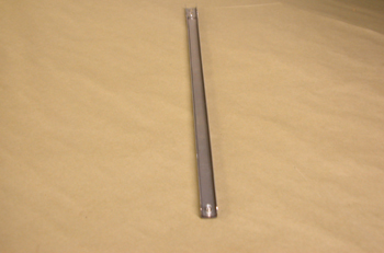
Our stiffening tube was spot welded together. We then cut out the back half of the tube on each end to install into the door to enable us to stitch weld in place on the ends.
At this point we then cut out strips of 20 gauge and laid them out for 2 qty pieces, which were then bent at 90 degrees. Two channels will now be welded together to form the rear portion of the window channel. This is where the rear edge of the glass will slide up and down.
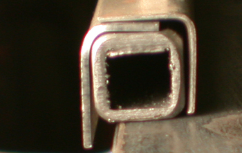
Using 1/2 inch square tubing as a form for our desired width the two sections will now be clamped in place to be welded. This is the exact width needed for track glide material on both sides, yet keeping 3/16 laminated flat glass tightly supported and still running smooth up and down.
We weld it all up while clamped in place then allow to cool.
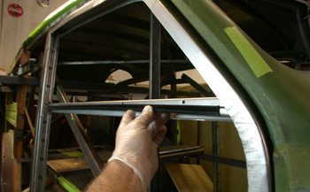
To show you the exact location we fit the channel in to the driver side rear door edge. As seen it allows ample clearance for our door catch which we will mount at the end of this article. We will now install and weld this channel into our passenger side door.
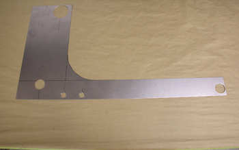
We now build unique shaped channels that are two inches on one side, and one inch on the other side. We also bent a small lip on the two inch side to support the outer door panel and inner interior panel on their respective pieces. This is the "Window Sill" where your arm would make contact if you had it resting on the door while cruzing.
We first install the inside window sill to the door frame and tack welded it in place. Note the holes, these will be used to retain the window fuzzys, which will also make slight contact with the glass inside and outside allowing a smooth glide against the full width of the glass.
As seen we trial fit our window fuzzys and cut them to length for mock up to be sure everything works correctly.
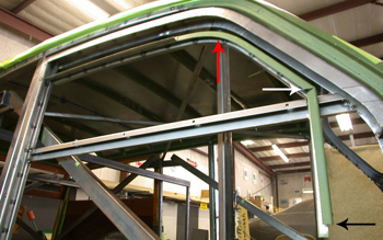
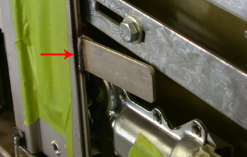
We built another channel and pie cut one section (white arrow) to allow our overall width of the side glass. We shrank the upper section (red arrow) to match our curved roof line. As seen at the (black arrow) this channel needs to be lengthened to the very bottom door brace to complete the front side channel and support the glass through its complete movement. This section needs to be removable to service the door if the power window mechanisms or glass ever need replacing.

For mock up purposes we installed 3/16ths wood as our temporary glass to check our fit. You can also use 3/16th lexan but it is more expensive After we install the outer window sill section we will check for proper clearance and then tack weld all the channels in place.
We open up the door and as seen the outer sill is now welded in place with our finished width determined and the overhang or excess top window channel is being cut off.
After taper is achieved and the inner and outer door frames are spot welded together the top window channel is tack welded together also. We then slide the plywood and channel up and down to check alignment. All is good so we go on to the next phase.
The materials are laid out for the upper power window motor support panel/beam. We will drill holes and add our support plates. This will also act as a support beam.
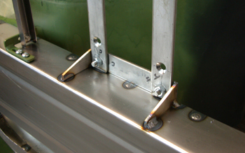
Qty of 2 - 1 wide x 1/8 thick flat bolt bars in stainless are fabricated for the power window regulator. They are then spot welded to the upper support panel/beam.
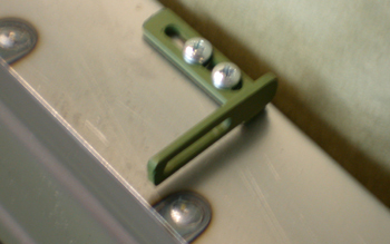
Threaded inserts and a custom two-way bracket keep the bottom of the removable front channel discussed in caption #18 in place.
We took another piece of 20 gauge and formed the channel needed to extend to the bottom as in #18 for the front section of the window channel. This piece is removable and adjustable to facilitate removal and or installation of the door glass. We simply installed 1/4-20 threaded insert nuts on both ends
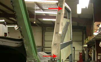
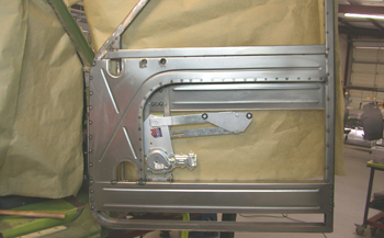
As seen the power window support panel/beam unit is installed and tack welded on both ends. In addition the window glide channel is also installed behind the beam. A ½ inch bead was rolled in to the panel for rigidity and the outside edges are bent on the brake at a 90-degree angle for extra strength.
We took two sections of one inch stainless strap 1/8th thick to be used to attach our power window motor. The stainless up rights attach to the upper sill top, side to side panel brace/beam and the lower main door beam. Note the counter sunk holes to hold the power window regulator in place. This adds clearance in an already tight confined area.
Stainless steel flats were fabricated along with a qty of 2 1/8 x 1 Stainless bolt plates. They were then welded at the top window sill and lower main beam for gussets.
The power window motor is attached and checked for fit. She looks good so on to the next step.
On the rear upright for the window regulator a tab was welded on for the window down stop. Note the slot on the regulator arm allows for adjustment if needed.
To tie it all together more material was laid out to fabricate an inner door panel support. This will also support the door a bit more so no flex will take place when powering the window up and down. It will also hold the future interior door-opening lever. In addition access holes were located in key locations for adjust-ability, these were simply cut out with a hole saw.
The edges of the access holes were stepped and rolled with a ½ inch bead to stiffen the panel.
A ½ x ½ angle strip was fabricated and then fitted along the outer edge using the stretcher/shrinker and spot welded in place using clamps to complete the panel.
As seen we have fitted the inner door panel brace and welded it in place. The door is just about done.
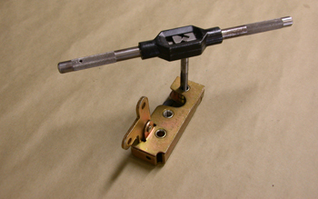
Because of the close tolerance in our door to provide enough space for glass, power mechanism, and door opening rods, a nut and bolt combo would interfere with the window channel. We tapped the latch mounting holes and heli-coiled them thus eliminating the need for a lock nut. Our recessed Philips screws will tighten the unit in place just fine.
We chose small bear claw latches that included door panel corners pre-notched for the latch.
After laying out the latch location with a sharpie we are ready to cut and install the latch.
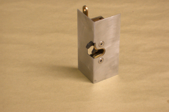
notch was cut in the Rear door edge. To fit the unit in. A cap was fabricated to finish off the cut out section and then welded in place.
The latch plate was then welded in place and ground smooth. We are now ready to go on to the one off hidden outer door handle