
Build Tips
Cowl Hood
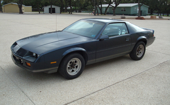
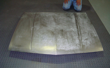
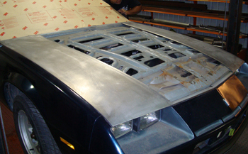
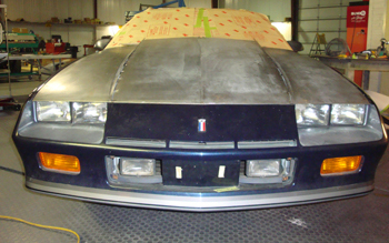
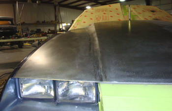
The stock Camero awaits its new Cowl Hood upgrade. Bone stock she is some what flat with the exception of a few body lines.
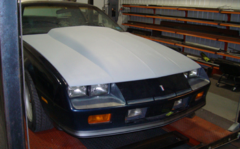
The owner bought this fiberglass cowl hood in hopes of a muscular face lift but it has an unnatural look and a lot of fit issues. One being too short front to back by over 1 inch. In our opinion the cowl section is too high looking with a rounded top edge that goes down in to a hard line at the bottom and this does not flow with the rest of the Camaro design.
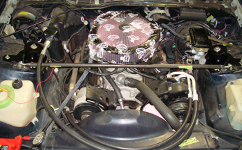
The first step is to find out the minimum clearance needed between the top of the air cleaner assembly to hood panel. We are using a K&N open element on this particular project.
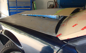
We stripped the hood to bare steel. Time to analyze what we are able to do, taking in to consideration the natural limitations of the panel and the filter clearance.
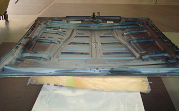
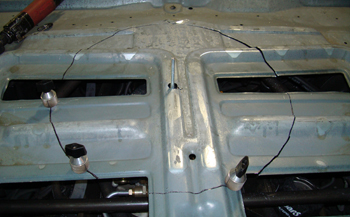
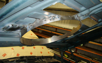
With the hood flipped over you can see GM built a lot of reinforcement to compensate for the thin outer panel which is 22 gauge at best. We cut away all the caulk / adhesive holding the outer panel to the inner structure to release them from one another.
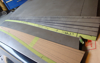
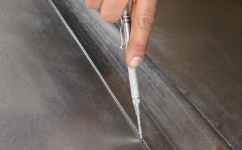
We drew out the basic areas with a sharpie where we are going to slice.
At the front and rear edges of the panel we are going to cut about 3/16ths of an inch just inside. Note the 3M weld protection paper on the windshield.
After cutting the panel off we are ready to measure our air filter to hood clearance.
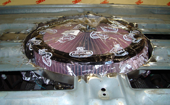
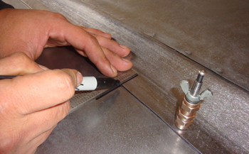
We located the air filters center by marking and drilling a 1/2 inch hole. As seen an extra long carb stud protrudes through the hole for marking purposes. The engine sits off center in the chassis to the passenger side by factory design. Lou cut a circle one half inch outside the outer filters diameter for extra clearance room to allow for engine torque side to side.
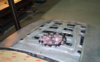
We installed the filter and it clears fine during opening and closing.
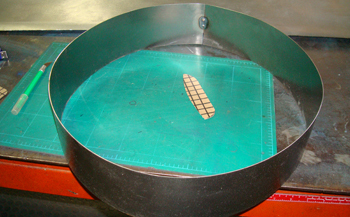
We cut out some metal and rolled it in to a circle the same diameter as our cut out in the hood.

Next we fit it to the hood then tack welded it in place. Using a sharpie we marked the wavy irregular shapes of the inner structure to the new metal. We then cut the tack welds free, removed it and trimmed it to fit.
The result is a stiffened inner panel that custom fits the contours. We only tack weld every inch at this point. We will fully weld it later.
Everything still fits and clears well so on we go.
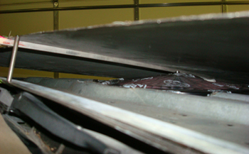
The next step is to lay the original center panel back down in place and tack weld the very front to stabilize the panel. We raised up the rear to check for minimum clearance and to establish the " LOOK" we are after.
It is determined that 3 inches in the center and 2.5 inches on the outer edges has the most natural look.
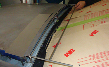
As seen on the under side our air filter wing nut has approx 1/2 inch of clearance. We bent some aluminum bar stock to match the hoods contour and then inserted it down the center to stabilize the panel.
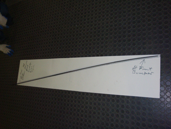
Next we start on the sides by bending 1/4 inch rod to match the slope we were after. Making a template for exact duplication on both sides is mandatory.
As we fit the wire it is starting to take shape. Note the extra length behind the hood toward the wind shield. We have not yet determined the full length that the cowl section will be so we will leave it long and trim it later.
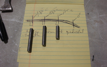
Some increment rod material was cut to act as pillars in order to strengthen the main rod so it will take the weight of the panel.
We tack weld them in place and start the process of checking our fit regularly to be sure nothing moves.
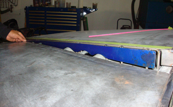
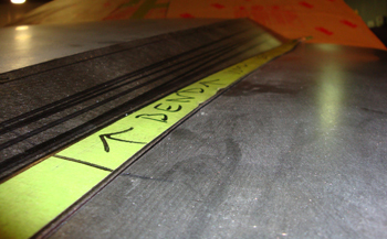
Once all the rods were in place on both sides of the hood we fabbed some 18 gauge reinforcement walls to fit in and around the wavy slopes of the inner structure. The top edge was matched to the same template that the 1/4 inch rods were made from.
Yea man, she looks good at this height. Sooo- Let's continue.
The next step is to make a 1/4 inch wire match the wind shields shape as this will be used to reinforce the very back of the panel or cowl.
We tack welded the rear cowl reinforcement wire between each side rod and then laid some mock up board on the top to get an idea of what we want the cowl to look like front to back.
We determined that 4.5 inches longer then the stock hood was the best distance. We cut out some metal to fit and are ready to tack weld it in place.
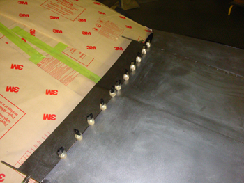
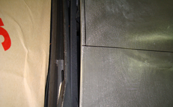
We used panel clamps for the right gap. This is important. 1/16th works good and allows the metal to expand during the weld process which avoids warping.
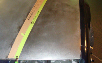
Next we mocked up the side profile to get an idea of the way we want the panel to flow in to and out of the hood for the most natural look.
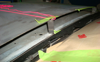
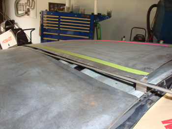
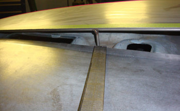
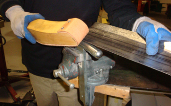
We marked our template where the bends should take place then transferred it on to 20 gauge steel. The green tape shows the bend line. We want to establish this line first to get the panel to sit down against the existing hood section matching the same contour as close as possible.
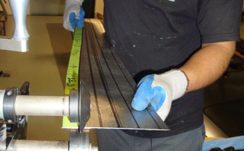
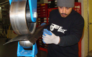
Starting from the rear of the panel we used a roller die that is very angled. This die forces the metal to kick up slightly with 3-4 passes doing the job.
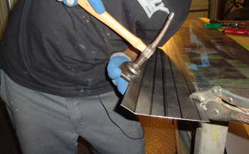
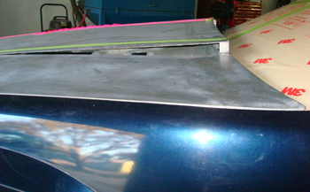
Mani hammer and dollies the edge in a few places to get it to touch dead on.
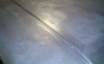
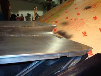
As seen it sits on top of the G.M. metal pretty decent. On to the next phase.
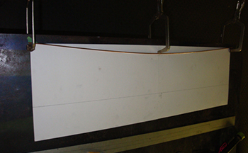
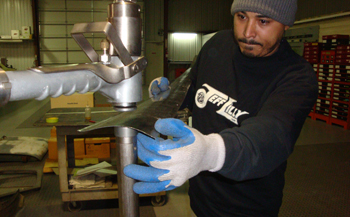
On to the English wheel to form a gradual roll from the top of the cowl section down to the lower section of the hood. Using a very tight radius wheel allows us to form a contour as quickly as possible on such a small piece.
The edges tend to get a little wavy when the wheeling is performed so using a leather faced slapper and a t-dolly Mani adjust the shape where needed.
Using the planishing hammer he curved the panel a bit more to get that "just right look."
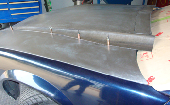
Clecoed in place she fits the panel nice.
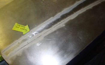
Once he was satisfied with the fit he carbide scribed the panel where he will slice then fit the orig G.M. Metal to our new section.
In addition he drew a cross line to know the exact fit front to back during the final stages.
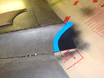
After fitting and tack welding the new side sections in place we made a template that we felt gave the best overall corner transition.
It looks good and aggressive but subtle at the same time.
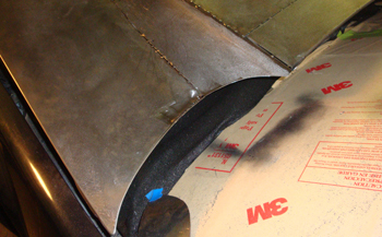
This angle shows a sweet transition.
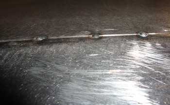
Everything is tack welded in place so we simply continue tack welding as seen until all is joined.
It helps to blast the areas to be welded for quick and precise spot welding on a panel as fragile as this.
Finish welded and ground, Nicccceee.