Chassis
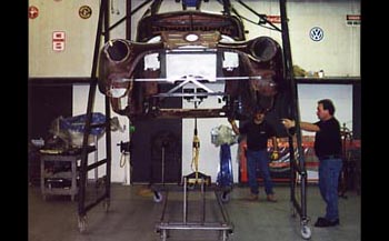
We start off with building a cart to stabilize the body and to allow us to raise and lower the body for ride height, body rake and set up the wheel base for the new custom chassis. Doc is dropping the body down onto the cart using our mobile a frame body picker and adjustable attaching system of which is electric winch powered.
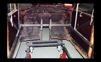
Doc built a cage in the interior to keep all the metal and wood from moving, Notice the hand adjustable sliders For moving the body up and down easily.
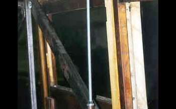
In addition an adjustable push pull system was installed to tweak the body for proper alignment due to the rusted out condition of the body metal to start with.
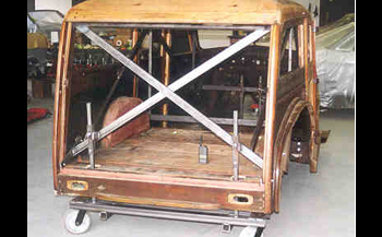
Taking a look at the rear section you will also see the adjustable sliders along with an X brace to keep the wooden capsule from moving while lifting body on and off of chassis.
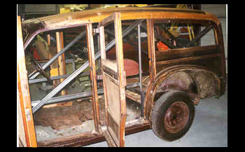
Finally the roof to floor braces tie every thing together.
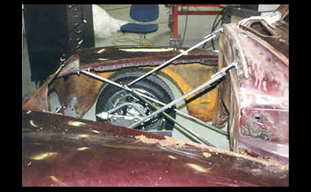
1/2 rectangular tubing allows us to hold the front clip metal in place for mock up and is also adjustable.
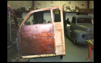
The customer has decided to convert the Woody from a 4 door to a 2 door, so we will do a quick mock of the door to check for symmetrical size shape etc. We cut about 1/3 of the rear door, removed the B pillar and added the 1/3 of the rear door to the existing front door.
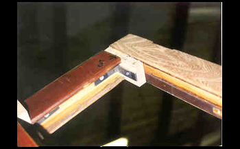
We added L braces to support the additional weight.
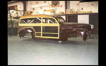
With the door mocked up and front clip installed we start to get a look at what she may become. Her name by the way is "TRICKWOOD" Notice the hanging plumb bobs, these are used to establish front axle center line of the body. In addition the qter and new door size was masked off to create the desired body panel lines. We used flat black paint to fade out parts we want to diminish and used green masking tape to amplify the changes.
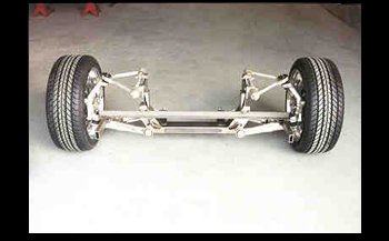
Our mock fitted front suspension clip is ready for its initial fit for tires, rims etc. This must be determined beforehand. We will now roll it under the body to take a look.
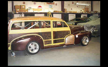
All wheels and tires are rolled in place. Our adjustable cart allows easy changes to get the right look. We then photograph the car from many angles and different stances etc. At this point we send the pictures to the customer to decide the stance he wants. After we get the nod from the customer we measure for wheelbase, track width and how low the body will sit so the frame can be built to fit this "one off" custom Woody, also known as "Trickwood."
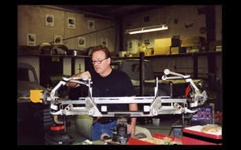
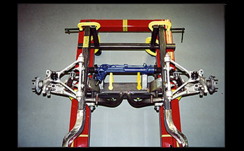
We have measured and fabricated the front suspension system using late model Corvette Control Arm mounts to the tubular cross member. Doc is setting up the system and checking tolerances
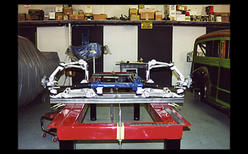
We then set up the front suspension onto the frame table for squaring and centering using our steering for a centerline off the chassis table which is dead on square. Note: the string runs the length of the table.
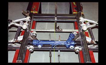
Our table was designed with an open center for easy access of clamping, measuring etc. From here we check our geometry and layout the wheelbase using the string and squares/levels. We then clamp into place for no movement.
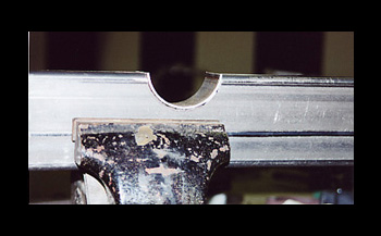
Our next step is to fabricate the front frame rails. They consist of a qty of 2 - 2x4 rectangular pieces of tubing. We cut them extra long as we will trim them to the exact length at a later date.
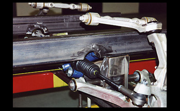
All of our measurements from here on out will come off the centerline. After mocking up our front rails a relief cut will be needed to clear the tie rod travel on the rack and pinion steering, Using a hole saw we cut a notch out of the frame on both sides. We then cut a piece of round tubing and fitted it to the rails and then welded it in place. This caps it off nicely while retaining the structural integrity and providing ample clearance.
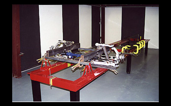
Next up we clamped every thing to the frame table, squared up, leveled out at our predetermined height to keep the body where we wanted and radiator support height etc. We then proceeded to tack weld control arm brackets and rails together
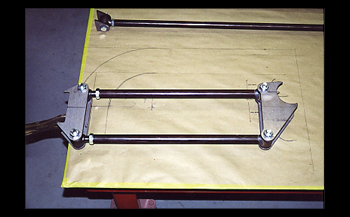
We have already rolled the front suspension components into place and set the rear tires and wheels inside the body with a pvc mock up axle to predetermine our wheelbase. Now is the time to fabricate the rear rails/suspension etc. Our desire is to build the rails to keep TRICKWOOD low for looks as well as handling.
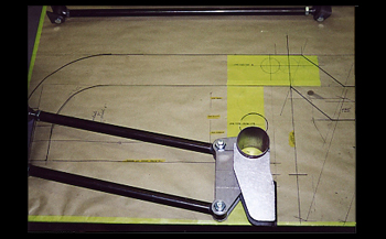
We assembled our 4 link components and mocked them up on 36 inch masking paper. As seen we figured the full suspension travel and have drawn out our patterns for our rear rails. This enables us to know exactly how much clearance we will have before we actually cut any steel.
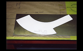
We then transfer our patterns to steel then cut and weld our 120 material to make the exact radius needed to fit this one off TRICKWOOD beast NOTE! We used a small section of exhaust tubing to duplicate the rear axle and shock perch!
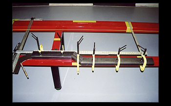
We laid out 2x4 rectangular tube and sectioned it to achieve our desired ride height and clamped, squared and welded it together. We then placed our inner radius plate down on the level surface of the chassis table along side our rail using our T-Square straight edges for perfect alignment then applied a few tack welds.
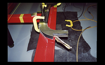
We attached the lower wall to the inner radius plate by rolling it and tack welding it in 1/2 increments making it conform to our custom radius shape. As seen we are now rolling the top plate in place while we tack weld it and the lower side wall to the inner and outer radius simultaneously in 1/2 inch increments .
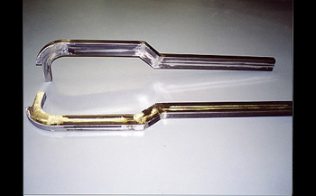
Everything is double checked and welded in solid then ground smooth. The end result is our 2 rear frame rails are ready to go. We are now ready to build the main cross member which will stabilize our new rear frame rails and 4 link suspension
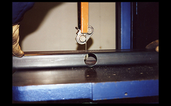
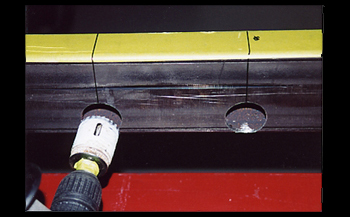
On our main cross member we start with 2x6 rectangular tubing. Using a hole saw we bored a hole on the top and bottom the same diameter as our drive shaft loop tubing. We are now sawing it down the middle providing us with a perfect pocket to fit our drive shaft loop.
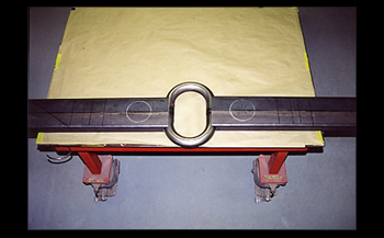
We tack weld it in place using squares etc as before. NOTE! The 4 inch circles scribed into the main cross member for 3 inch exhaust.
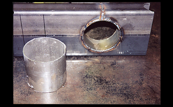
We then took a 4 inch hole saw and cut out our diameter on the drill press. Using 4 inch tubing we cut, fit and welded it inside to maintain our strength and structural integrity.
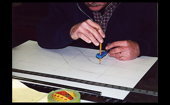
At this point with our established wheelbase we are ready to widen the frame in the main body/cowl area. We need to spread and drop our frame rails down and out. We start by laying out our patterns full scale.
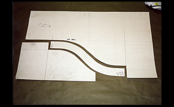
We cut out paper board templates and transferred them to .120 steel. We then cut them out and are ready to bend.
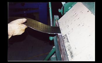
Doc curved the inner and outer side panels using the Box Pan Brake by clamping and bending at 1 inch increments. This is done the exact opposite on each side to form a left and right frame drop.
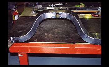
He drew out the upper and lower sections the same and bent them as well. The result is a custom "one off" set of frame rails to achieve the desired results. We will now attach them to the front rail section.
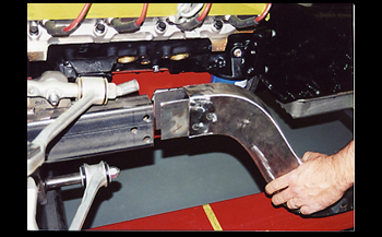
For alignment purposes and to achieve a strong bond at such a critical point we drilled three spot holes through the frame rails and at the ends of each frame drop. In addition .120 thick rectangular plate was inserted in to the drop section on both inner and outer walls and spot welded in place.
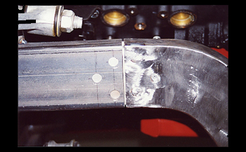
We then slipped the end into our front frame section. We then repeated this at each end of the side/center rails to finish attaching the front and rear cross member together.
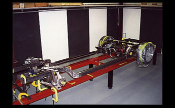
We simply attached the long 2x4 rectangular tube side rails the same way as the drop off's and then installed the Ford 9 inch rear end in place. We now have a rolling chassis.
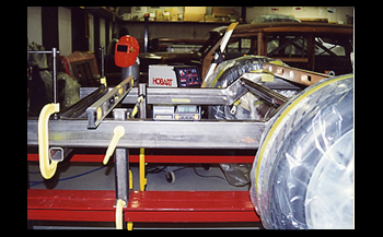
We used a hole saw and bore a hole on the inside of our rear rails and fitted a shock bar in place. At the very end of the rear rails another 2x4 tube finishes out the main frame.
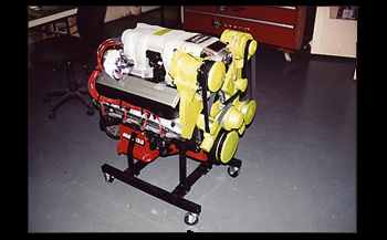
Now that the main frame is in place and clamped to the chassis table we need to proceed with an inner tube structure to support the Wooden beast from tweaking. Givin the fact that a 502 Cubic Inch motor with 610 foot pounds of torque is going into the saddle we are in need of more than a basic square frame.
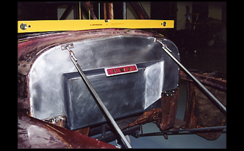
A custom firewall recessed back 4 inches will give us ample distributor clearance for the big block. Of course we made it a smoothie and we will also round the upper corners to blend in with the Woody style.
We installed the motor before hand and measured accordingly, the motor mounts were then built by connecting the frame rails to the cross member. Doc designed the mounts to set the big block low and back as much as possible for the ultimate weight distribution.
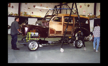
It is now time to drop the body down to check the firewall to tranny motor clearance and to measure for the lower inner structure tubing just inside the main rails. In addition we will also note our measurements on the floor to trans tunnel metal.
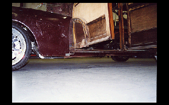
As seen the frame rails are the same height as the bottom of the rocker panels. Low and tucked in nice, just the way the" Doctor" ordered. We simply used square tubing clamped to the frame rails to hold the body up into our approximate position and shimmed accordingly.
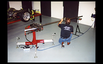
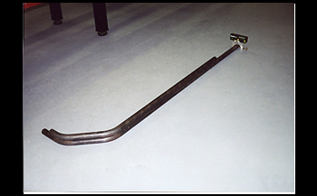
We removed the body again for easy access and layed out 1-5/8 seamless tubing with identical bends for both left and right sides of the inner frame.
Chassis
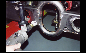
Once again we used a hole saw to bore holes at the proper attaching points for maximum strength and alignment.
Chassis
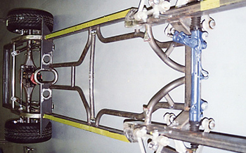
As seen the tubes are in place. We also used 1-5/8 tubing for the trans mount cross member. At this point we have only tack welded the tubes in place.
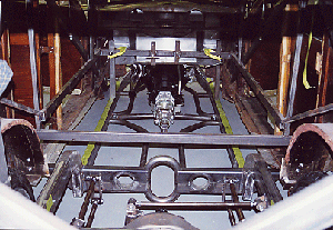
We now take our measurements for the upper inner frame structure which will then be fitted with custom floor sheet metal and body mounts. As seen we reinstalled the motor and tranny to check for clearance!
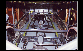
Doc bent the tubing to support the frame and allow adequate clearance for the shift linkage, drives shaft, exhaust and fire wall.
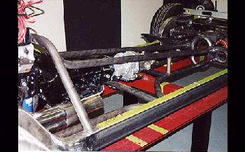
The view from the rear shows frame supports in place tack welded and the quick remove tranny cross-member for any servicing needed in the far out future.
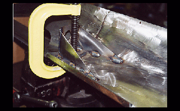
It is now time to fit the body to the frame and fabricate frame to body mounts. At the bottom of the outer fire wall we fabricated new body mount supports to keep the body our desired height and support the rear of the front clip.
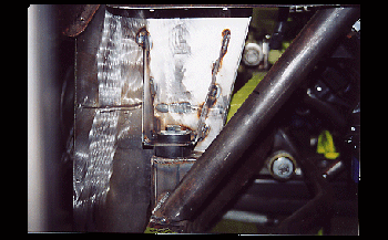
The finished fire wall body supports are in place using urethane bushings at 1/2 inch thick to keep everything stabilized. As seen we tied them into the transmission crossover tubing. This will really stiffen our frame and eliminate any flex.
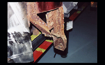
Typical rust out shows the "A" pillar thin but still intact. This must be rebuilt so we will use this for measurement purposes. In addition we can now determine the correct length of the frame rail to body mounts of which will be fabricated with a smooth transition or "arched" frame mount.
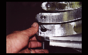
Our custom made frame to body mounts were built from 12 gauge cold roll flat sheet and bent to our specs. Notice the recessed Allen head body mounting bolts, flush and looking good.
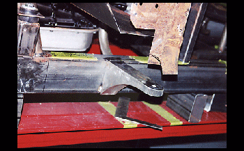
We tack welded the very front mounts in place after squaring them up. As you can see they are rounded at the ends and possess a very smooth transition from wide frame to narrow top. " Hey, even the body mounts on "TrickWood" have to be cool!
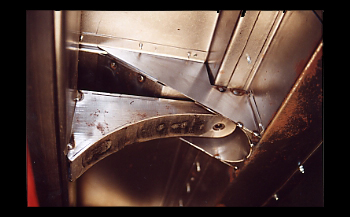
The body mount and rocker support has been fabricated and tack welded to the floor metal. Doc built 3 of these per side between the A pillar and B pillar. These special supports tie in the floor and inner rocker to support the weight of the body and roof while eliminating any flex that would normally occur with a 600 plus foot pounds of torque. This particular mount is right below the door post. There will also be a roll cage attached to this frame mount that will go up into the roof and tie into the roof cage. In addition the upper driver seat belt restraint will tie into this post also so strength is of the utmost importance!!!
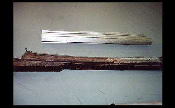
Off to the rocker panels. The originals were obviously wasted and needed replacing to adapt our new chassis to the body and support all the weight.
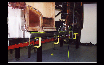
Installed the rockers have a nice fit and the wood door clears every thing well with a nice gap. In addition we have installed an 18 gauge A-pilliar door hinge cover. We simply repeated the same on the passenger side.
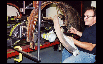
In order to fabricate the rear frame to body mounts the rear wheel well needed to be removed and built to accommodate our 18 inch rims and low profile tires while allowing the body mount clearance.
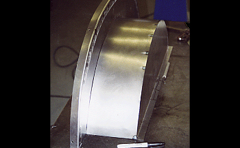
Doc fabricated from his templates new custom wheel houses and they are ready to install. Keep in mind we are still using self tapping screws to assemble new metal panels on to the body and frame for pre fit purpose. They will all be removed and welded permanently then media blasted, epoxy primed and reattached.
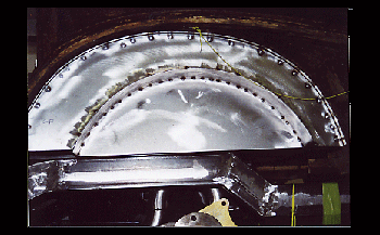
In place and looking good the rear wheel houses are rock'n.
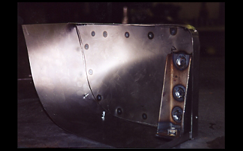
This is the Torque Box we fabricated. It is installed directly in front of the rear tire! It has been designed to accommodate the arched frame mounts and rockers which support the body weight in this area.
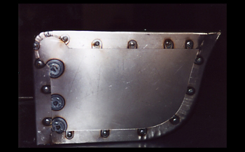
Another look at the mount shows it boxed and tack welded. Doc used the power stretcher- shrinker to form this baby. Notice the various bends that were made to make it fit just right.
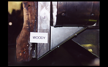
Once installed you can see how the frame mount extension, bottom wheel house and rocker attach to the to the Torque Box. The Chassis cross member sits just inboard to this area so it was designed to handle the demand that a heavy car with major torque will dish out.
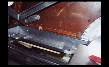
The rear or back half of the Woody is supported much the same but with the addition of boxed plates that will join the wooden structure behind the rear tire. As seen we have the boxed pans in place, using 3/8 plate he drilled out and tapped threads then installed recessed bolts through the frame to the body mounts.
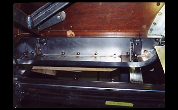
The frame mounts are a bit shorter as the Woody is somewhat narrower in the rear frame section. Notice the 90 Degree angled brackets to stiffen up the sides and support the wood.
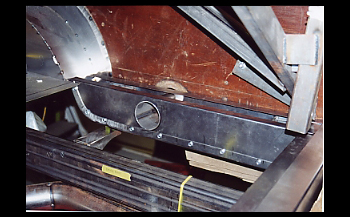
On to the passenger side we bored a hole in both halves with a hole saw and installed 3 inch exhaust tubing between the inner and outer walls. This was designed for the gas tank filler neck to pass through providing scuff protection and eliminating any gas fumes from entering the cockpit of the high horse Wooden beast!!!.
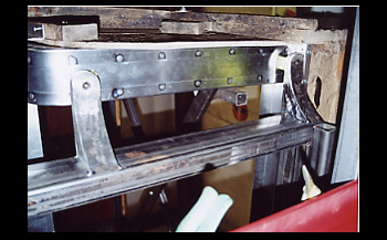
We take a look below the passenger side support and we see the arched frame to body mounts tack welded in place and ready to be welded up solid once we have mocked, inspected and tack welded all other mounts. Remember measure twice cut once for "profection results"
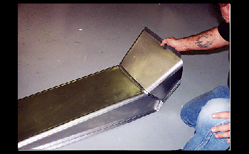
Doc went on to the trans tunnel. First he mocked it up in paper board around the chassis trans tubing and gave 1 inch clearance in keeping with his blueprints. The trans tunnel to fire wall section was fabricated to accommodate foot comfort to gas pedal with no foot and or ankle twisting problems during those extended drives.
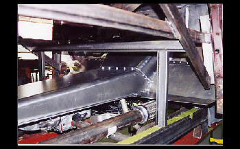
The tunnel fits nice. We are only installing it temporarily with self tapping screws so we can continue to fabricate the remaining floor and make adjustments if needed!
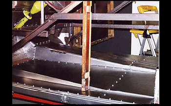
The toe boards are installed and the floor is coming along nicely. We will install the sheet metal from rockers to frame / body mounts at this point.

