
Build Tips
Camaro Rear Seat
Here we go, the first step is to do a mock up of the concept I have in my mind. I want it to flow from every angle with no interruption.
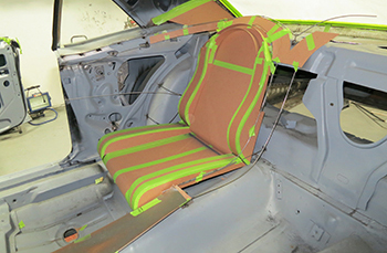
The rear seat is going to compliment our front buckets with a continued voluptuous style.
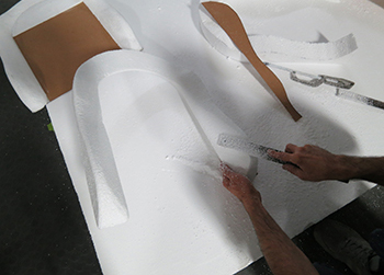
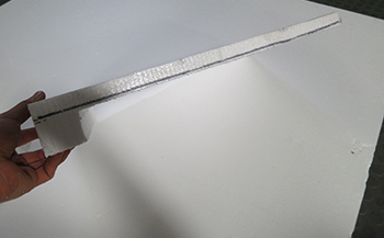
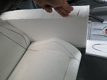
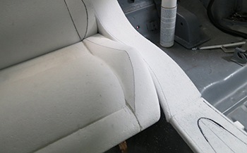
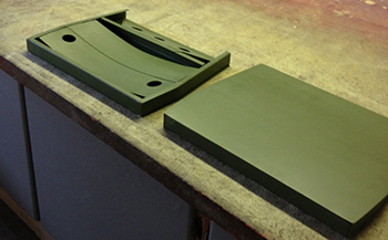
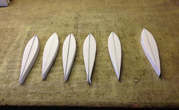
Using Polystyrene in 1 lb.., 1.5 lb.. and 2lb densitys we can shape what we want before building the actual foam seat. We lay our outer perimeter chip board mock up on top of the foam and get ready to cut.
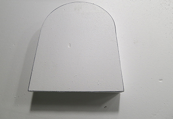
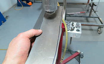
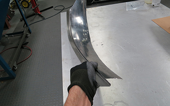
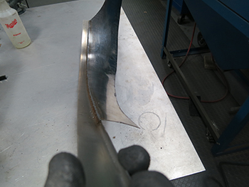
We used a hot knife to cut the foam, as seen it is Dead On around our mark.
After the hot knife we use a hack saw blade to cut out any tight inside radiuses.
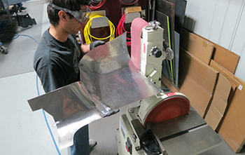
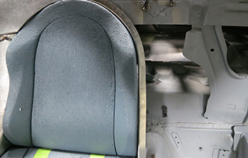
We then start to sand using 40-80 grit sand paper for our desired contour.
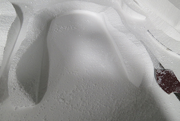
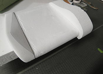
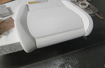
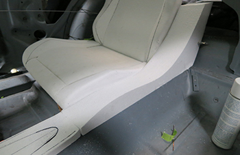
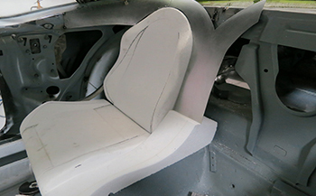
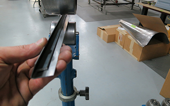
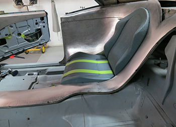
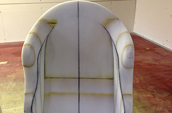
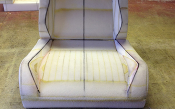
This angle shows the Voluptuous contours to resemble our custom made front buckets.
We also use a rasp which is a rough cut file to bring the foam down to our liking in a timely manner.
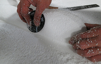
Something as simple as a round grinding disc can give you the control to shape multi contoured areas easily.
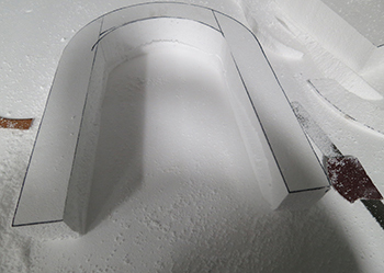
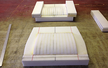
The initial fit shows it coming around nicely although it is still a bit bulky. It needs to be a little sleeker, so we will cut some more.
The bottom and back inside sections also need to be cut and formed. This will also give the side bolsters more support.
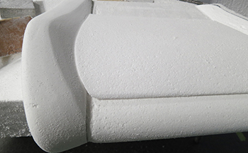
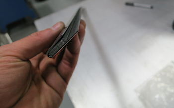
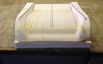
The side profile shows the back section has more material at the bottom where the upper and lower sections will meet.
You get the main pieces close to what you want and the rest is all art work. File and shape to create what your minds eye has envisioned.
A hack saw or hot knife will work, if you need a smooth edge and you do not need to sand it much then the hot knife is great but if you are a fast worker and need to file it more any ways then a hack saw blade will be fine. We use all the tools for maximum results.

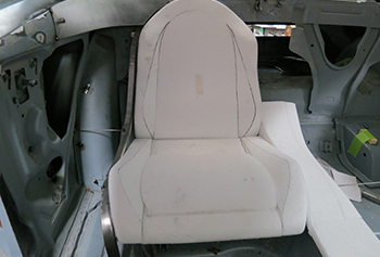
Keep sanding until you reach your desired goal.
t is decent but I want it more contoured so we have some more work to do.
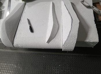
A little more work was done and then we hi lighted the contours with a sharpie marker. This allows a better 3D model of how it is really shaped. The camera does not reproduce images in 3D like the human eye does so we use highlighting to get a better visual image of where we are at.
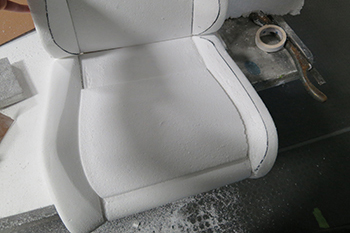
The bottom section needed a bit more tweaking so we filed a bit more and are now sanding with 120 grit for a finer finish. Note the center section has a leg support much like a lumbar support on the top or back portion.
The 2 lb. foam is more dense and files slower but more precise as seen the finish is smoother and has less pinholes.
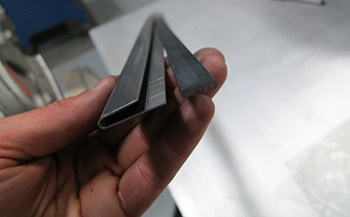
We also angled the wedge areas where the top and bottom sections meet. We have to end up with a product that can actually be built in foam. Foam has a lot of "give" to it and requires a 1/8th gap between sections to allow the cover to stretch and move over itself some what so we strive to achieve those results.
We start with a large chunk to decide on the console section that goes between the buckets. We simply trace the foam against the rear seats side profile so we can get close to matching it.
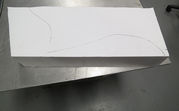
Traced out on the foam.
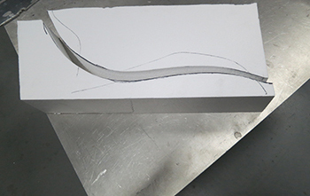
Quick sliced and ready.
It is coming along and we have a close place to start.
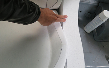
At this point in time shaping the center console for size and looks between the rear buckets is imperative. This also allows you to adjust the seat sizing if needed.
The transition is decent but still needs a lot of work.
Looking pretty good, a tweak here and a tweak there and before you know it you got it.
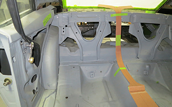
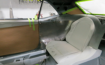
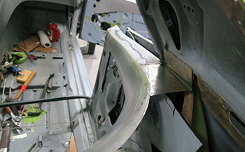
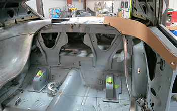
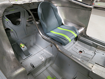
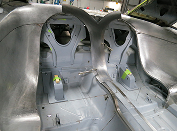
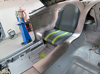
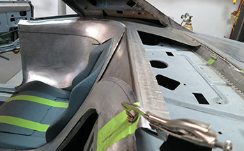
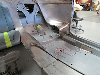
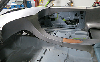
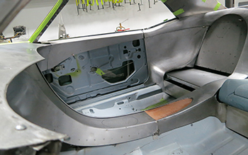
We decided it was time to build some of the metal around the seats to get a better idea of how they will sit in to the confines. It is often wise to build a little on this part and a little on that part until they flow together correctly.
It is coming around and gives you an idea of what I have envisioned it to be.
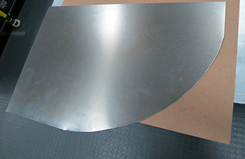
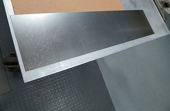
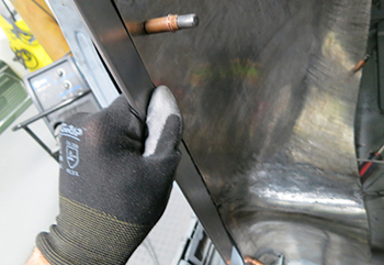
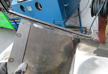
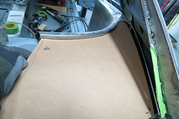
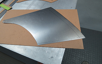
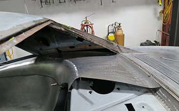
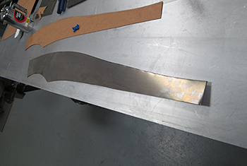
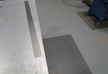
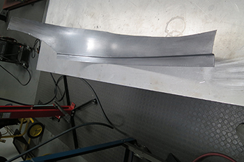
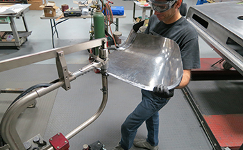
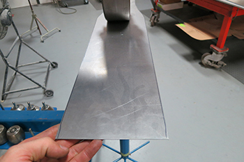
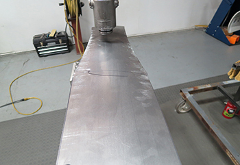
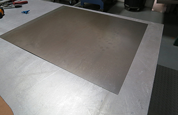
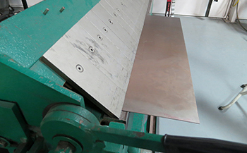
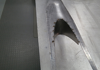
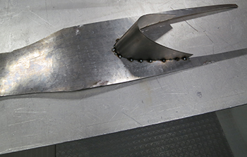
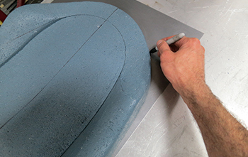
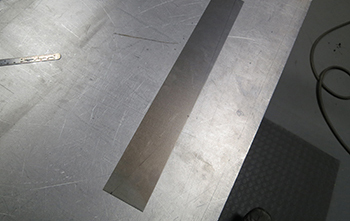
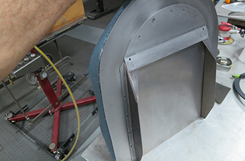
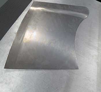
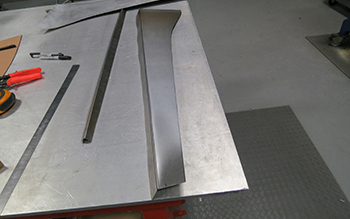
Now it is time to start making the large side panel, Sam cuts out some 20 gauge and begins the process.
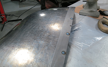
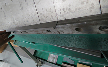
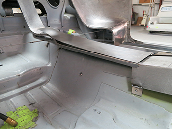
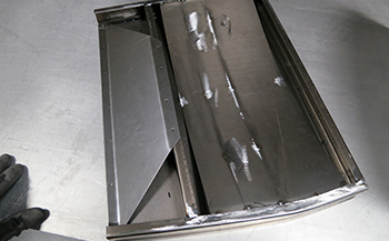
It starts out flat and straight and will require some serious manipulation. Notice the angle channel built to match the outside shape of the seat foam. This will encase the seat and give the proper gap all the way around.
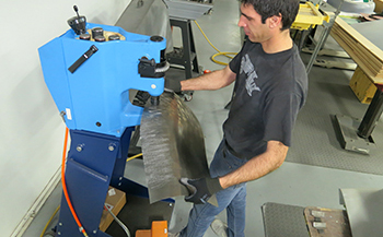
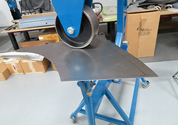
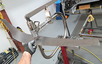
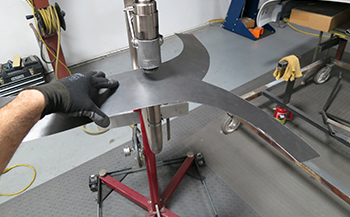
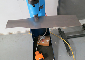
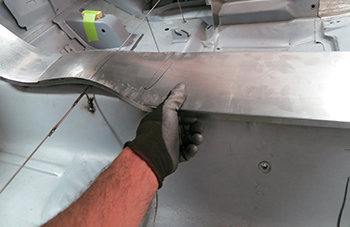
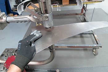
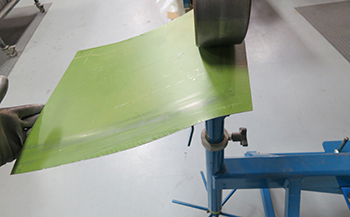
The Eckold Kraft former is needed to bring it all together. Mega shrink capabilities to 11 gauge if needed.
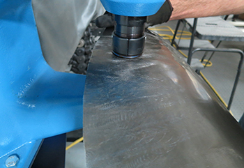
Powerful deep throat stretching is the only way to move this much metal.
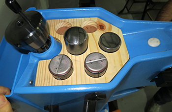
Different dies to get it done.
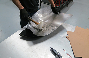
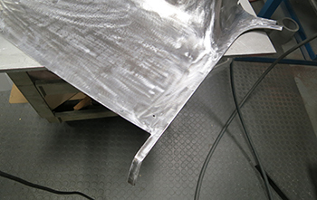
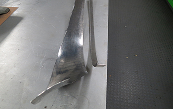
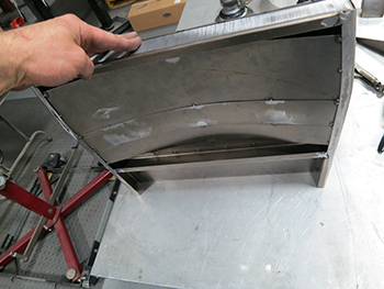
It takes a bit of Plastic mallet wailing on it to stretch it out in the center areas. Note the shot filled bag under it to allow the movement.
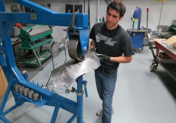
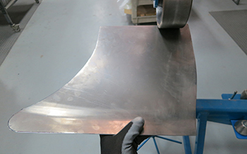
Wheel it in to submission Sammy. The Bully is on it !
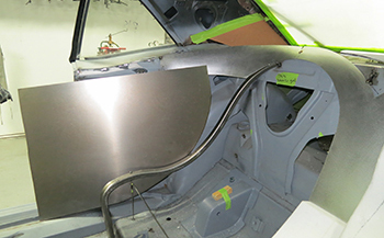
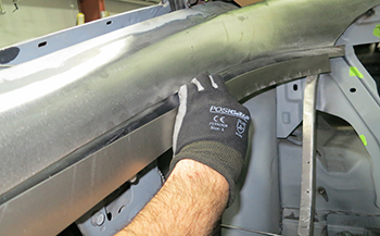
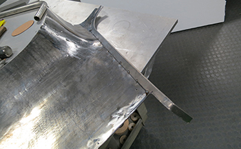
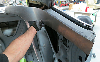
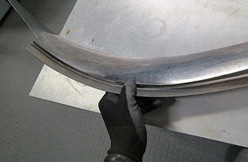
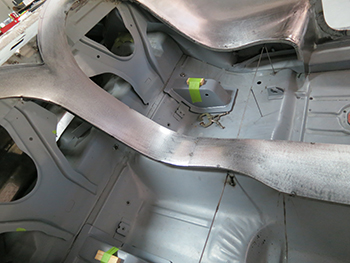
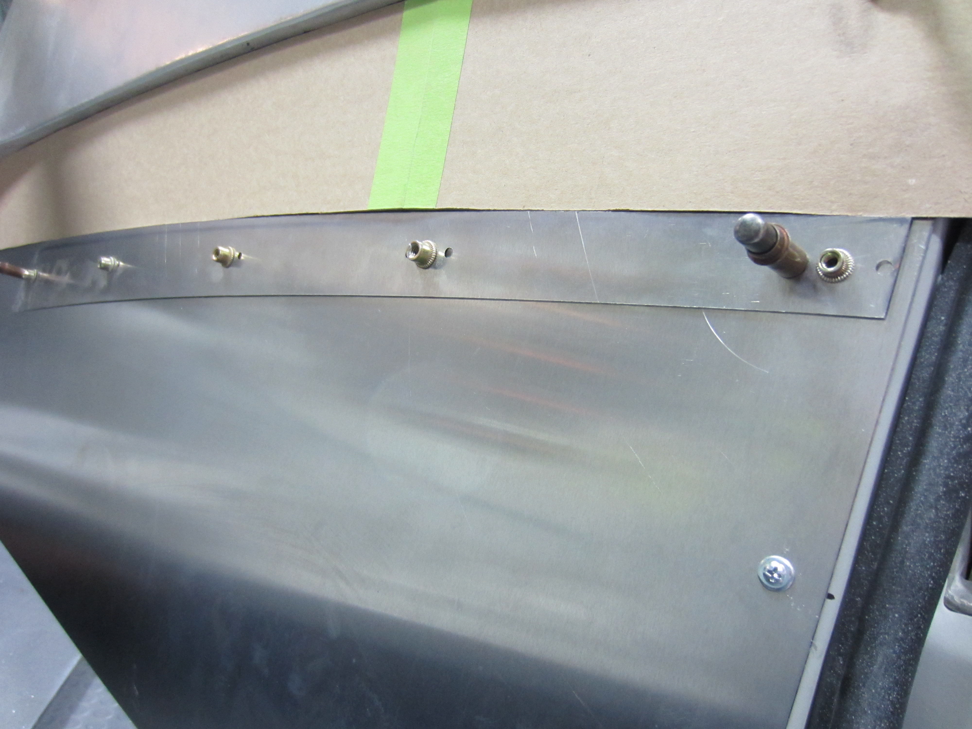
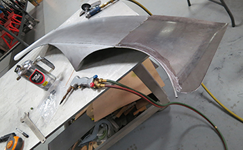
Coming around, currently we only hold it in place with clecos because we have to make some other pieces around it to fit in as a unit before any permanent trimming and or welding takes place.
Upper side panel is next.
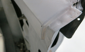
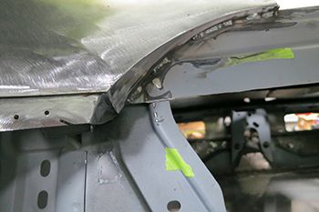
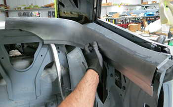
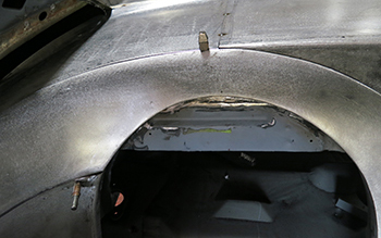
The original Camaro had a drop off to clear the door panel but our system is completely different.
The passenger side shows a slice and a drop so that the panel will be flush with out a drop off.
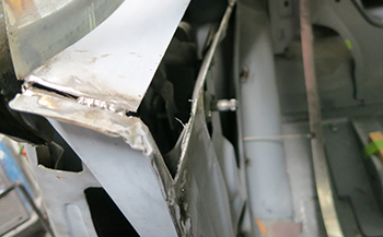
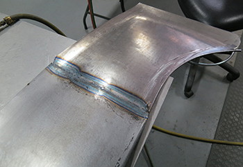
We simply weld it up and grind it smooth.
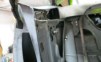
The original panel had to be cut away as our new one is much more concave.
The window cranks are seen and will need to clear so we have to go through the motions when fabricating away from factory specs. Every T crossed and Ever I is dotted.
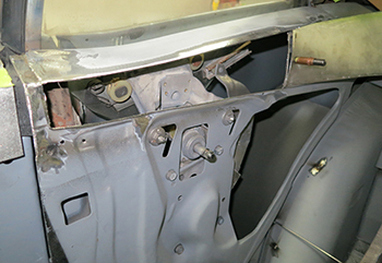
Sam fits a piece inside the opening and it looks pretty good.
It needs a bit of convex shape and stretching in order for it to fit the edges so more planishing is needed.
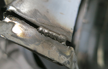
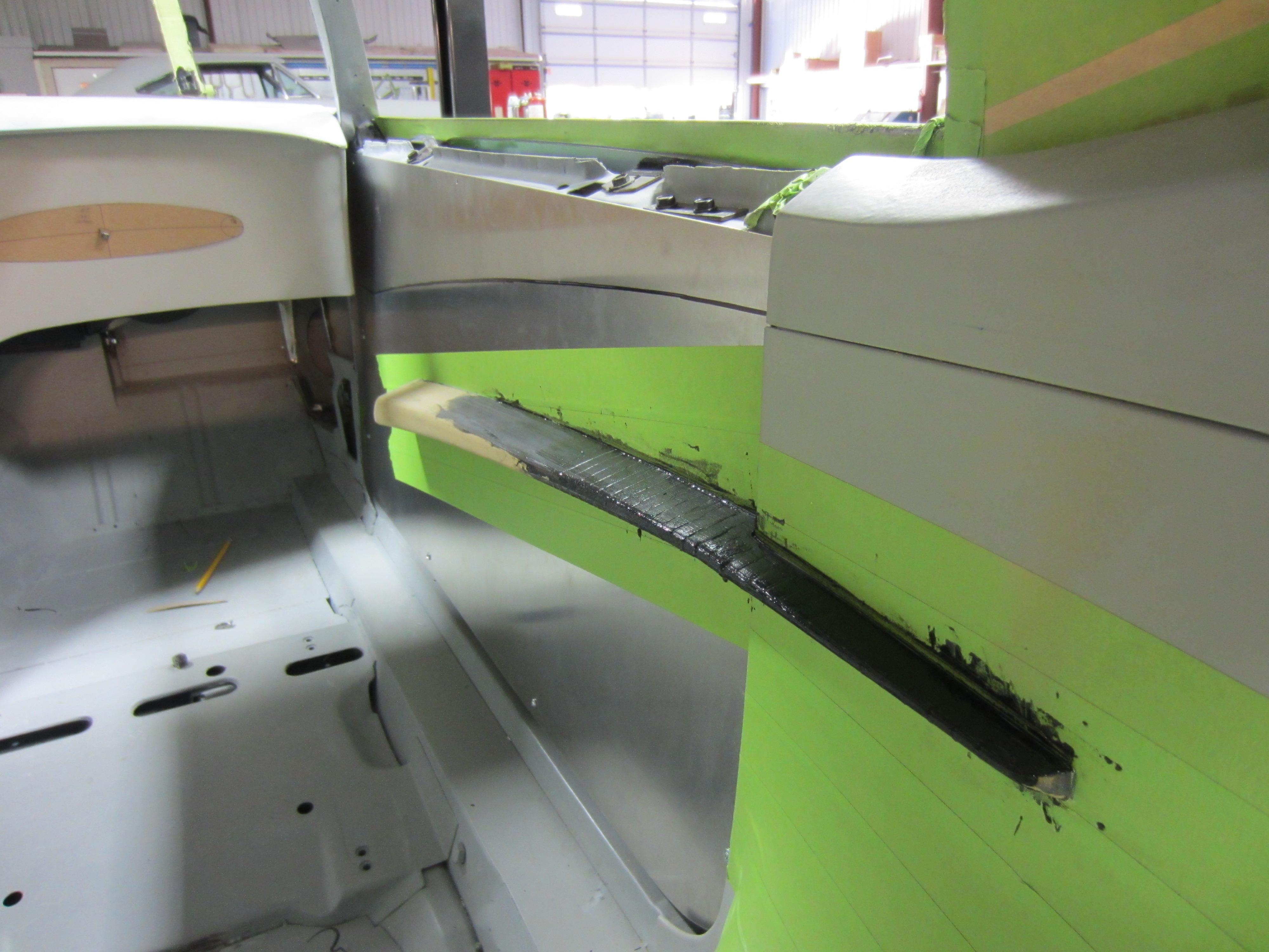
We are starting to weld it in place after he tweaked it to fit exact. As seen it flows off the door panel pretty well.
Next a channel is installed below the panel to stabilize it and to allow attachment to the larger side panel.
A bit of trimming and it will be knocked out.
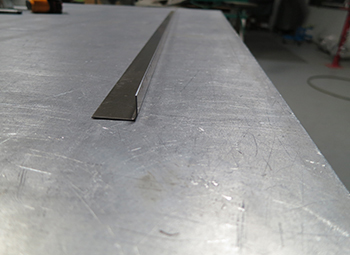
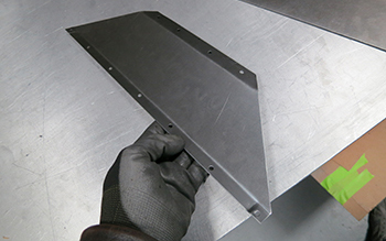
Using a piece of 18 gauge metal strip he contoured it to match the channel. This will be used to attach to the edge of the large side panel to help keep its shape.
He simply matched the larger side panel to the strip he just tweaked and it lays up nicely.
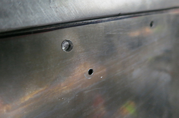
Next we drilled a few holes and now it can be welded together, which will also reinforce the top edge of the side panel for rigidity.
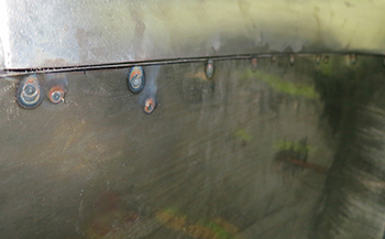
All welded up.
The back side shows how it is installed.
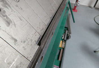
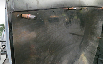
Next we need to attach the large side panel to the vertical edge where the panel ends. This will be used to slide the panel in place and finish off the edge at the same time. We simply slide a piece of 14 gauge in between the metal and folded around it using the sheet metal brake. To start off we bend a piece of 20 gauge strip to make an end cap to attach the large panel to the side.
As seen a slight 45 degree bend.
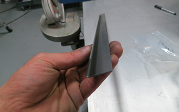
Simply insert a piece of 14 gauge stock.
Next roll the wheel over it.
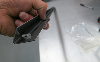
Flat as a pan cake and you have a channel.
Done deal.
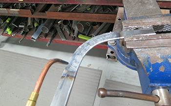
Heat the channel to make your bend to match at the bottom.
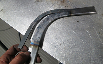
Remove the metal strip which kept it from kinking.
It fits around the side edge, finishes off the panel and will work great.
Sam tacked it in place to the side panel and it is ready for final fit.
Weld up solid and looking good.
The back side shows the completed channel is attached.
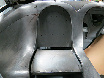
In place and looking great.
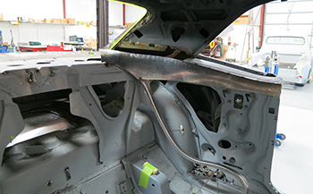
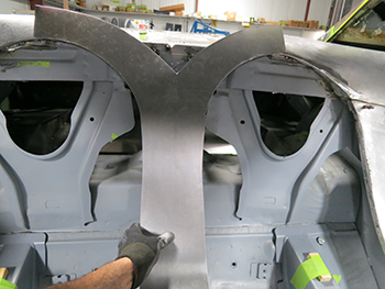
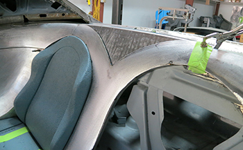
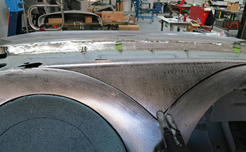
The crown fits around the seat pretty well so we welded in a finished edge. These sections will be permanent and non removable from the interior.
Same at the top tack welded in. Starting to finish it off also.
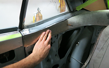
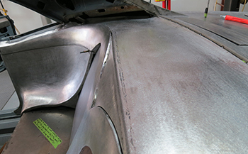
It flows from front to back decent.
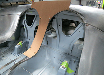
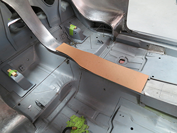
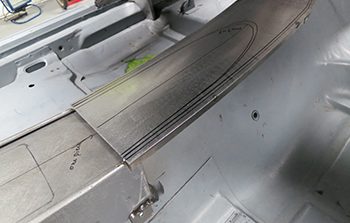
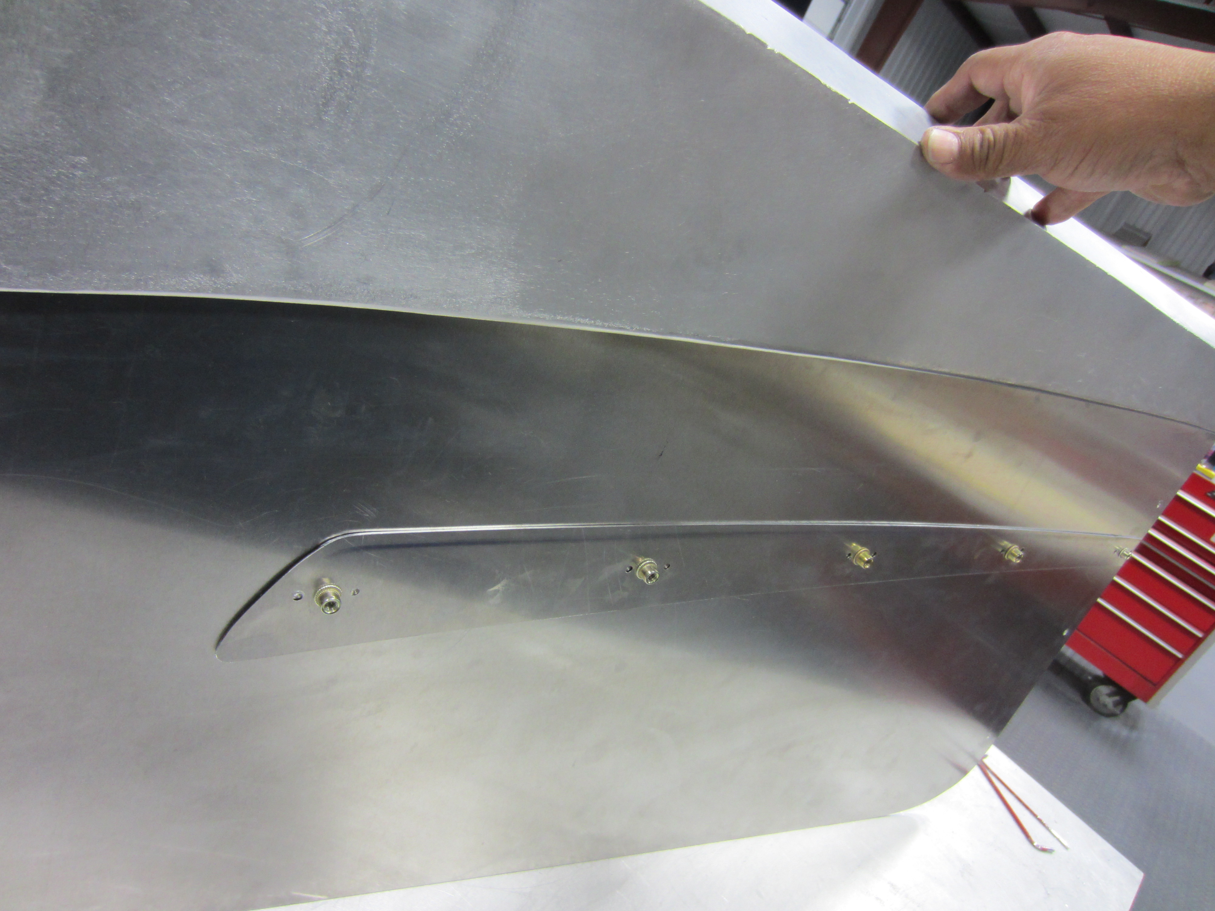
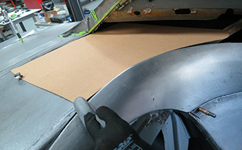
On to the rear deck, it needs to be removable to allow our custom molded headliner to be removed and installed. A template is made to give us an idea where we will end up with it.
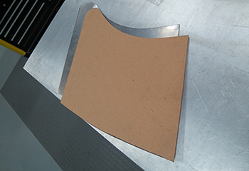
We cut out another piece of metal to match our template and it is ready for some action.
A bit of wheeling to get some crown or domed shape as some call it is needed.
It fits well and makes a nice gentle approach to the back glass.
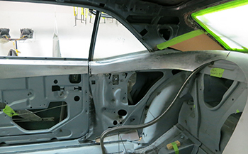
Time to get a bit more detailed showing what is done to make the upper surround come together. We cut off the old flat and square looking qter window surround and toss it in the G.M. trash bin.
Mock up is long and lean, curved from front to back.
Looks good so on to some metal.
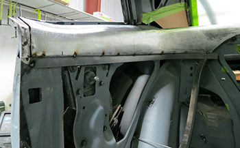
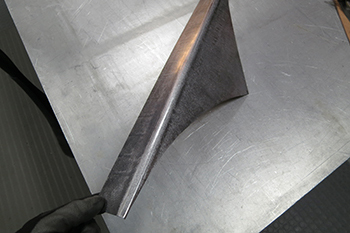
hey always start out rough looking but with the right design, correct tooling and the right hands metal magic takes place.
Just a slight bend gets the metal ball rolling as it is pretty simple to make when you have the gift.
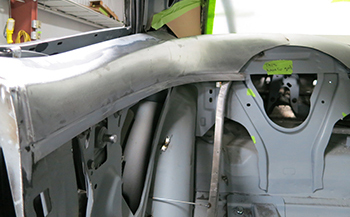
Planish a bit to soften the flow.

On the table you can see the smooth contour it is taking on.
Fits like a glove it is now time to reinforce.
A small strip to reinforce the edge.
On the brake it is taken to a small 90 degree bend.
Sitting along side of the panel it is ready to be combined.
Once it is an exact contoured match they can be welded.
It looks pretty good to me so time to tack weld.
Welded up and ready for metal finishing.
Finished off and ready to attach.
Now that is what I am talking about. Nice.
The side cover needs some final grinding on the edges for an exact fit.
Planishing just a bit for a slight kick out.
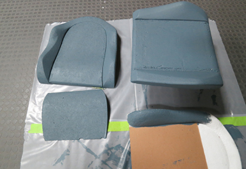
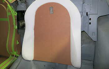
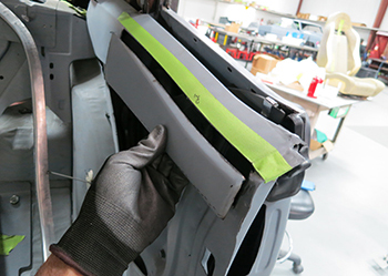
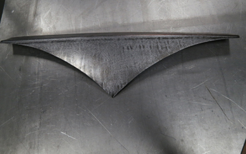
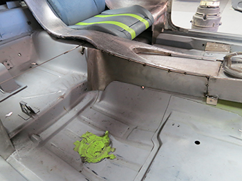
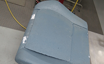
Time to paint our foam to help keep it intact and less fragile. Simply use water based latex paint, if possible do it in the shade of the color that you want the part to be so you can tell if you really like it.
Installed and ready for action.
Making the seat surrounds is easy with a 2 inch strip of 20 gauge metal, simply bent on the brake at 90 degrees.
Stiff and straight ready to be contoured to our seat. Never get the cart before the horse as I always say. The system we use to build these parts along with the correct order is a proven formula. You can waste a lot of time if you get off on a tangent.
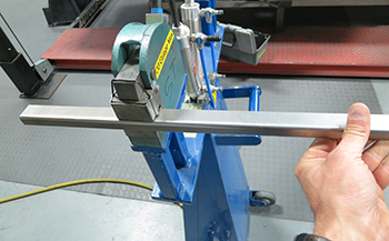
Mittler power Lancaster style stretcher and shrinker works great for these small parts.
A matter of moments and it is done.
Close up shows how easy it is to achieve.
Sam ran a strip down through where the console metal will be finished off and where it meets the front section.
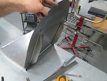
OK its time build the all important center section. Mock up as always.
Ready for some heavy metal music or movement?
Looks a bit wild but it will submit in the hands of the Metal Bully !
Planish in the right places and you get a part that sets itself "apart." Get it? I have a bit of dry humor to keep my sanity.
Roughed out but coming along.
Final section to combine.
Metal same gauge.
Laid out and needing some massaging.
English Wheel to give it a slight crown and then on to the stretcher.
Stretch it just on the outside edges to bring it down to a slight slope.
It is coming along but still in the rough stages.
Now planish it out just a bit.
Looking great.
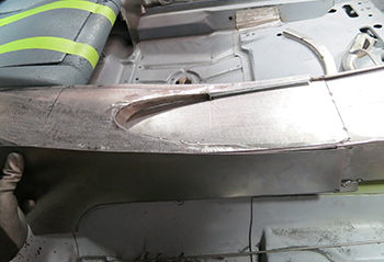
Smooth and subtle it flows uninterrupted. Just like I envisioned.
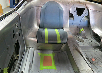
This picture shows the seat angle even better. Looks good and comfy too.
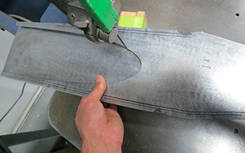
Time to fill in the top of the Vee to blend in to the rear deck. We cut out a large piece of 18 gauge and are ready to contour.
Measured and bent in the brake for a little less then 90 degrees.
As seen above the seat we simply trimmed it to fit as a filler piece.
This angle shows how we trimmed the top and ran it through the shrinker to fit in to our confines. It is recessed about 3/8th of an inch to give it depth which breaks up the overall crown between the two seat sections. This way it does not take on TOO BIG look.
Off to the console top as we want to give it a seam less look. Sam has it marked to allow the edges to flow in a circle but still be removable. Watch and see.
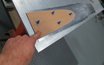
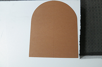
So we cut out a chip board mock up and traced it out exact.
Next we cut it out on the band saw right on the line.
We then added a curved wall to the inside to give it a confined area for looks and to stabilize it at the same time.
Upside down you can see how simple it is.
In place it shows the step down as it flows forward. This will give it the uninterrupted look.
On the rear center filler piece I wanted the edge to be a little softer on the drop off.
Sam used the planishing hammer with a small die to make it happen.
Refit it looks great and is coming together.
We are ready for the side panel of the console now and it is pretty easy, simply fill in to the floor and you got it.
Planish a bit.
Tacked in place it fills the void.
Now a piece under the seat for a filler panel. It is roughed out and unfinished but you get the idea.
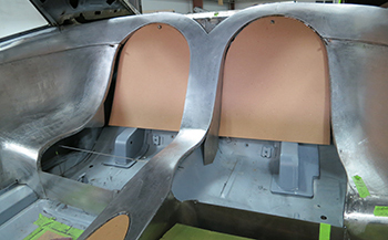
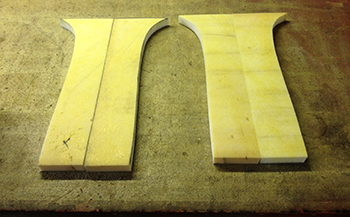
Next we made seat back mock ups in chip board to be sure both sides were exact matches.
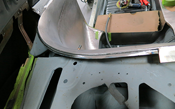
At the very back of the seat surrounds they have to have a flange to mount the rear deck panel securely, as seen we have fabbed a channel to support and connect the rear deck panel section. We simply took 18 gauge metal and bent it at 90 degrees and shrunk it to our desired shape.
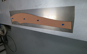
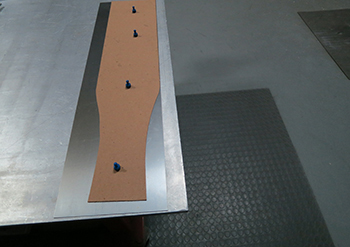
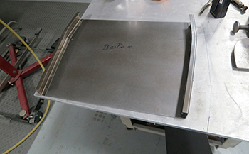
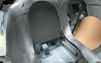
We laid our seat backs on top of some 18 gauge then traced it. Now we will cut them to build the actual support frames before we can build the actual seat foam.
We have our base made now so on to the actual structure.
Using a strip of 18 gauge 24 long 3 wide we start the process.
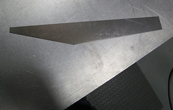
We cut an angle on it to clear the package tray behind it.
Bent 90 degrees and at an offset it will give us what we need.
Welded in place now another one.
As seen we are building it so it will sit at the same angle our foam mock up sits.
Add a section to combine the two.
As seen it connects it all together and is ready for same serious support.
Bottom section gets the same type of structure but differently shaped.
Installed at the outer perimeter much like a track system to handle the weight.
Now some arch supports to beef it up and handle the potential weight.
We need to figure how to connect the upper and lower sections at the precise angle to keep them in position so the outside perimeter of the foam looks right when finished.

Some support brackets on the cars floor are needed.
Back off with the camera and it shows the location of the parts to this point.
A wire was added to the back side to connect and also allow foam and materials to be attached.
one more section to the bottom for complete abuse protection.
Beefed up and ready to be welded in.
Bottom seat support fits great and snaps in with the upper section easily.
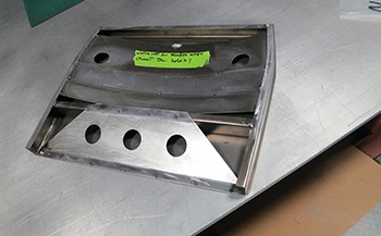
We decided to lighten it up a bit so we drilled some swiss cheese holes to accomplish this feat.
We already made the center top section so next we will fab the driver side rear section and weld them all together.
Tack weld, check fit and then solid weld.
Looking good.
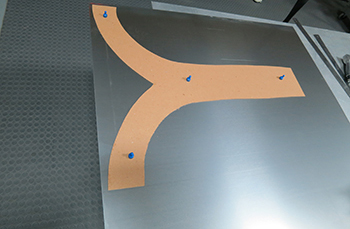
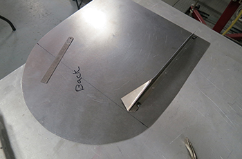
Make the template for the driver side panel.
Metal is ready.
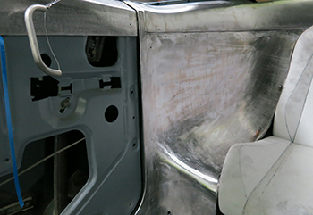
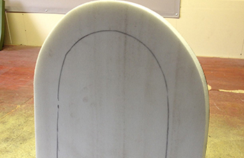
A bit of convex in the center and a concave shaped radius around the perimeter.
Wheel it out with a high crown.
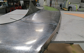
You can see the convex shape flows in to the concave shape very subtle as it goes up to meet the back window.
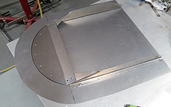
Looks pretty good, finally we can weld it up as a unit. Note the wire attached on the outer perimeter to give it the same rounded edge radius the center section has.
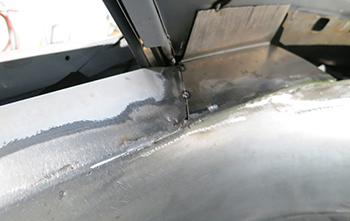
Gas welding using the hen rob is soft and allows wheeling the metal to smooth the surface.
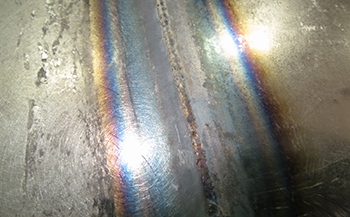
Close up shows how tiny and pit free this type of welding is.
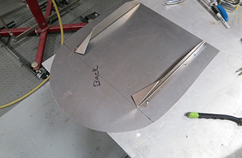
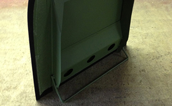
A small flange was added to stabilize the unit during installation and removal.
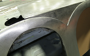
Next we have to add the door to make it flow in to the qter window surround. A simple piece was made to flow in and out unrestricted.
Flows like a river.
A Fish eye picture shows a flow like no other.
Primed up and ready for custom foam.
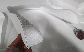
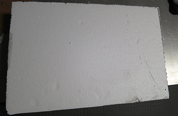
Raw cut foam is ready after Jan gets a hold of it to do his thing to the upholstery.
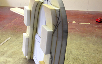
Building blocks of foam are added before any custom grinding takes place.
From roughed out to final grind the foam is matched to our Styrene mock up.
Glued to the metal frame.

Headliner materials will help support.
Thin 1 inch foam goes on the back
Wedges are next for the bolsters.
The same goes for the bottom section. Sort of like building blocks then contoured.
A bit here and a bit there.
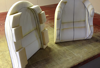
Contoured to perfection.
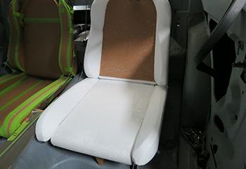
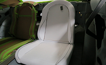
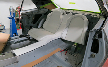
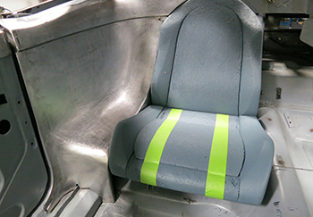
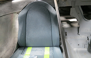
As a unit it looks and resembles the front buckets only a smaller version.
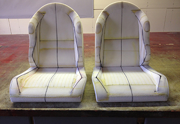
A perfectly matched set ready for fit to the car then custom matched upholstery when finished.
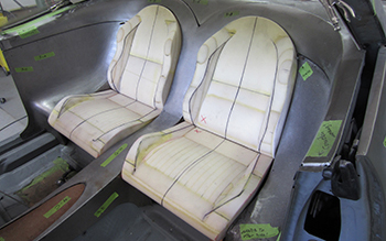
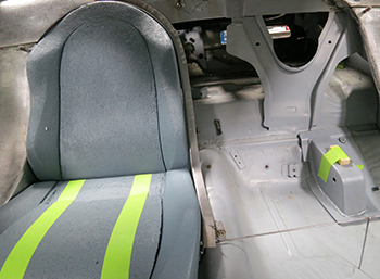
Looking good in the confines and an exact fit.