
Build Tips
Camaro Rear Fab #2
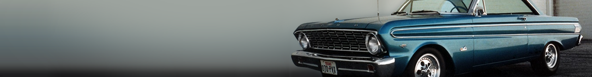
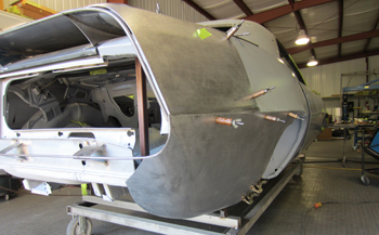
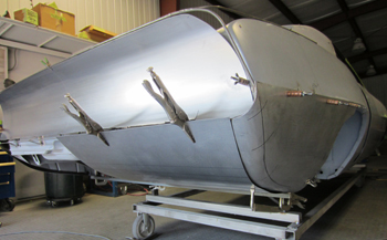
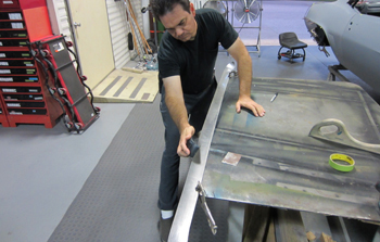
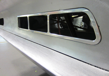
Sweet... its Saturday morning and the shop is quiet, a great time to start the wire forming buck that we will shape the metal to. Project " Dead On " awaits artistic instruction.
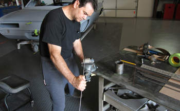
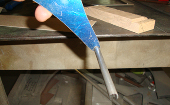
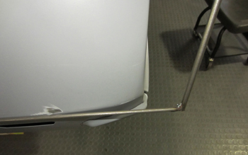
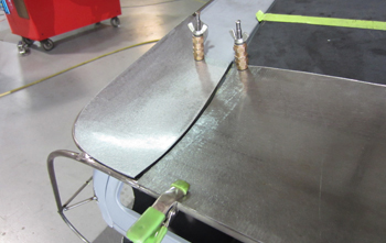
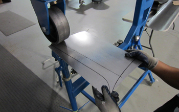
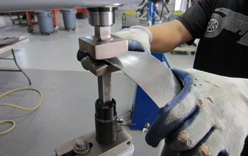
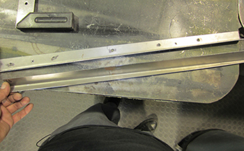
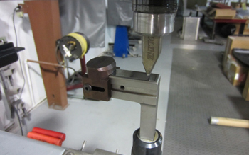
Using some tubing mounted in a vise I start the process by stretching some 3/16 th wire over a 2 inch diameter piece of tubing to match my mock up shown earlier.
Checking it against the mock up I get the top wire pretty close while checking the fit regularly.
The rear wire is starting to come together. Once the wires are made I simply make an exact duplicate for the other side for a perfect side to side match. Depending on the application and what thickness I want the edges to be I choose the appropriate wire size with 3/16th and 1/4 most commonly used.
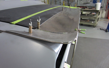
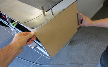
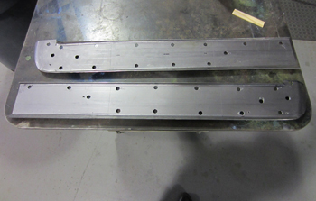
Once I decided on the spoiler transition I mocked it up in chip board and studied it. It is now time to cut them in metal.
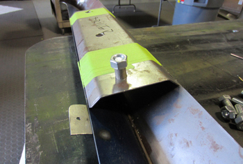
As seen we made them with tabs, these will be bent over to lay against the deck lid.
We cut some notches in the ends to fit the rear upper wire in to, this will keep it all stabilized.
As seen it fits the 1/4 inch wire exact.
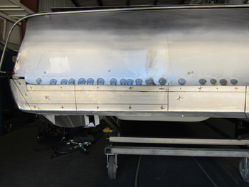
The tabs were bent, fitted and they are ready to tack weld in place and then we can install the wires that were fabbed.
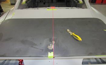
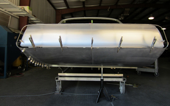
We also marked off the center line of the car so we can monitor the wire transition from side to side evenly.
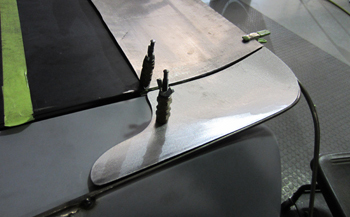
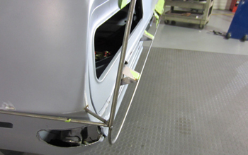
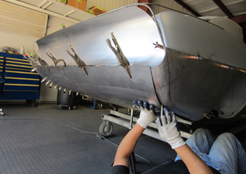
We joined the 3/16th inch upper qter wire to the outer spoiler 1/4 inch wire and tack welded them in place.
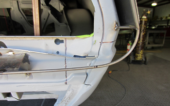
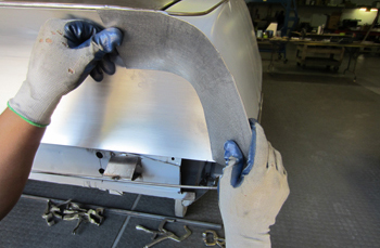
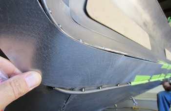
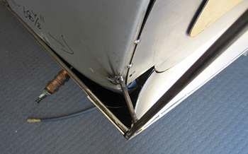
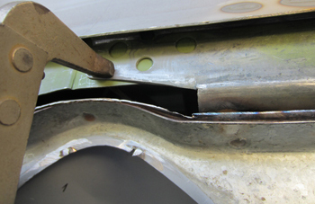
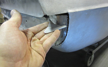
Coming off the side qter panel we joined a 3/16th wire to the outer 1/4 inch wire. As seen the qter panel is being lengthened approximate 1.5 inches at the bottom.
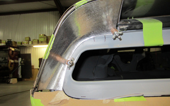
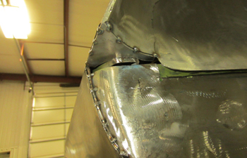
This angle from the rear end shows the wire coming off the top line for an "uninterrupted" flow in to the top wire section.
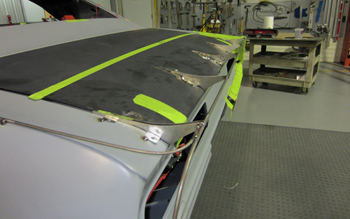
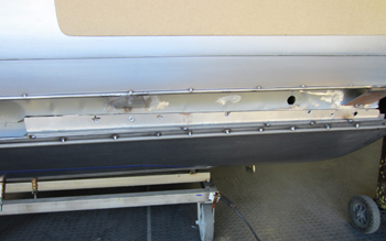
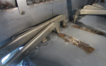
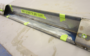
We added some spoiler braces for stability. For now we have to keep the trunk lid so it will open and close in order to have access to the inside trunk floor/walls. Eventually the trunk lid will we welded up solid to the qter panels much like a classic Corvette was and the gas tank will be installed from underneath the car.
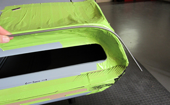
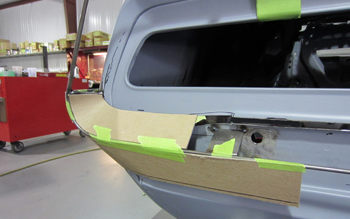
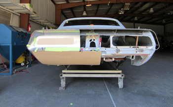
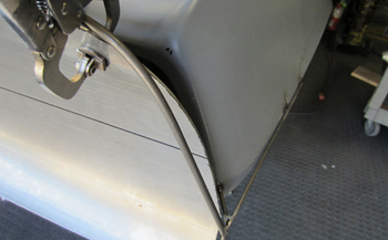
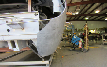
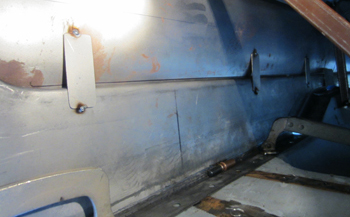
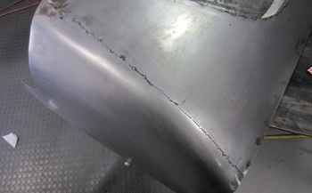
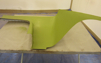
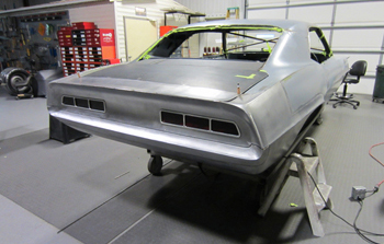
I am looking at a few different angles for the rear splash pan and this is pretty close to what I am thinking. In general I want to eliminate the "saggy diaper" look that G.M. had in it originally as seen clearly in the pictures.
All the spoiler supports are tacked in place.
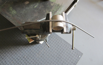
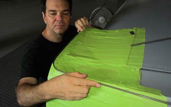
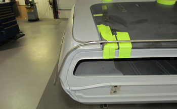
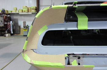
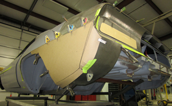
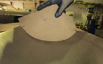
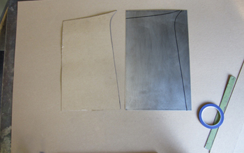
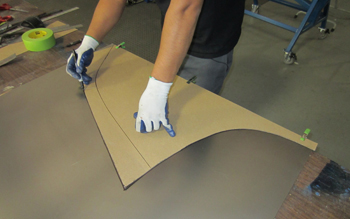
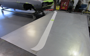
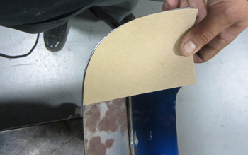
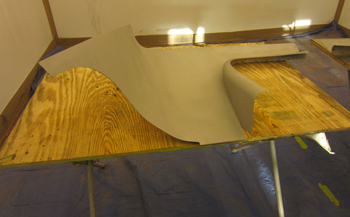
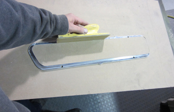
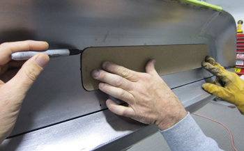
We've laid out a template for the rear spoiler. Using lite weight masking paper works for some of the templates depending on the shape. We also use 3M spark paper which has an adhesive backing along with poster and chip board which is the heaviest gauge and is light brown in color.
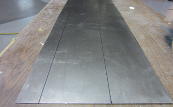
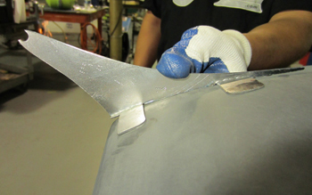
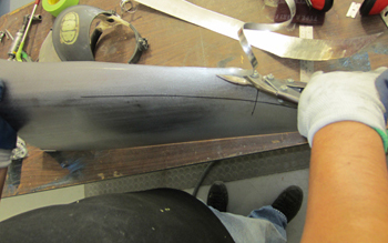
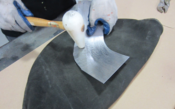
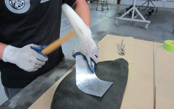
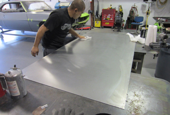
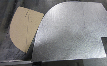
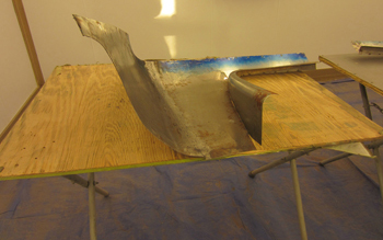
Metal is cut and marked so its time to shape the flat carbon steel in to a piece of art.
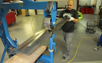
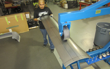
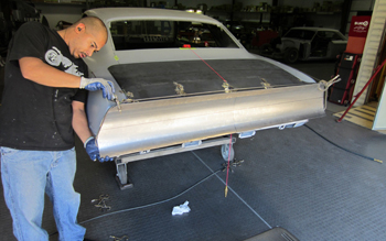
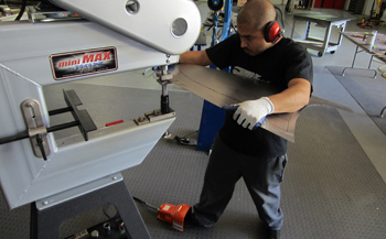
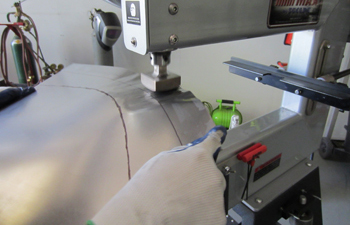
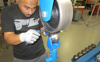
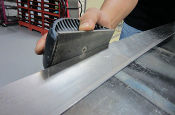
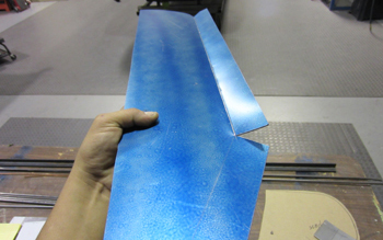
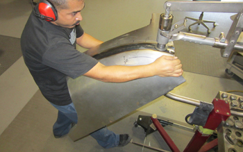
Using the English wheel we run the panel and get the basic shape to match our radius in the spoiler.
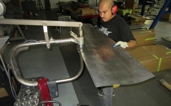
A bit of planishing on the edges to true up the panel is required. Ear muffs are much needed when running these machines as they are quite loud.

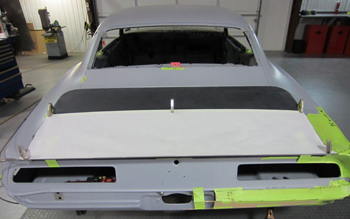
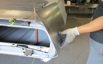
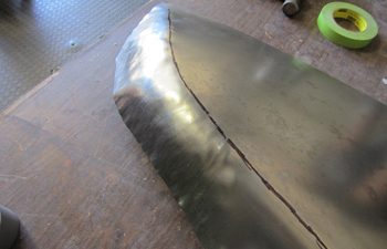
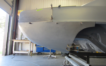
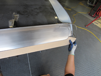
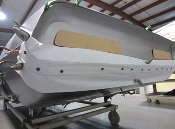
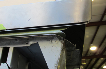
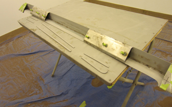
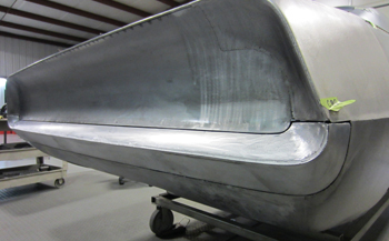
He laid it down and she is starting to take shape. As mentioned earlier the trunk lid needs to go up and down for access so this panel will be welded in last.
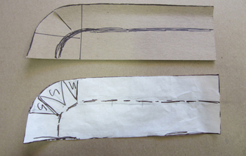
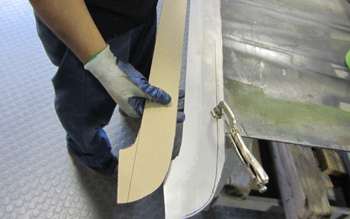
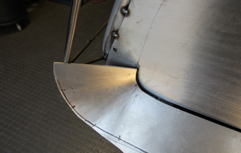
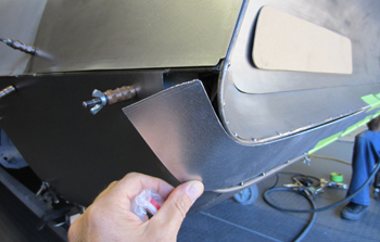
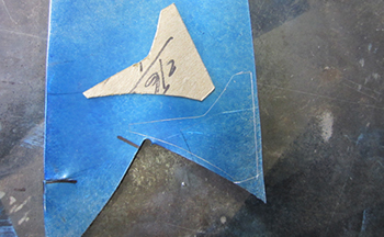
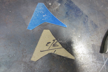
The end cap templates. This will fit in a recessed area so we added a relief cut to allow it to lay in place better.
As seen from the side, the relief cut allows it to sit in a relaxed position. He is ready to tweak some metal.
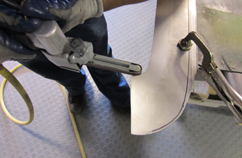
The right planishing die gets it done quickly as she takes shape in the hands of the metal-meister.
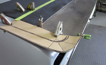
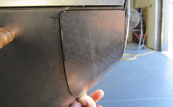
It fits great the first time. We hold it in place using wing nut clecos to study it and decide if it needs more attention.
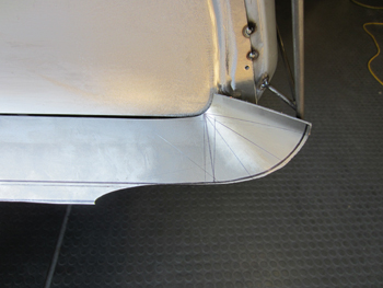
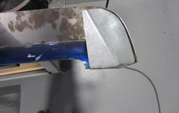
This angle shows the swooping front section which allows it to fit the original qter in the most gradual manner.

We also use mini close pin clamps that hold the edges so we can quickly check fit our work. You can find these at Lowe's and Home Depot where the orange apron boys hang out.
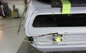
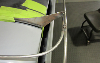
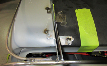
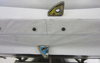
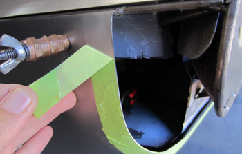
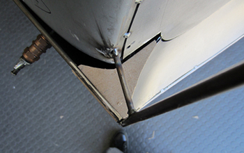
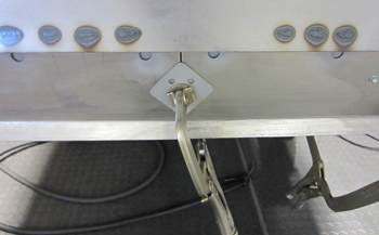
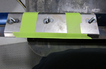
Next we fit and tack welded a few small braces to hold the wire in place where the original bumper mounting holes were located.
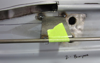
This close up shows our " basic " stabilization bracket. Simple but effective.
We also added a wire in the center where the wires meet to stabilize the area even more. Combined together these will help when the welding process starts on the sheet metal to hold it all in place.
The ends and center panel flow well together as " in a state of harmony." A what? I am a little weird, its the artistic side in me.
Next we mock up the bumper to see the space limitations and if we will be happy with the transition/angles.
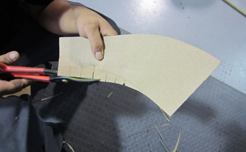
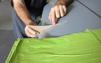
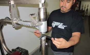
Mani cuts some relief cuts in the inside taillight panel template to start the process.
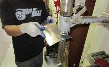
As seen it fits pretty good so we feel it is time to start the process with a sample piece in metal. It has so many angles that we need to see how the metal will react in the tooling.
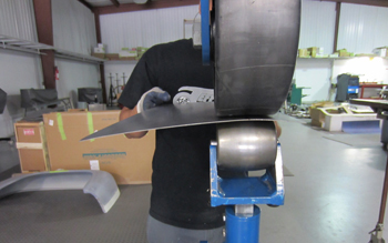
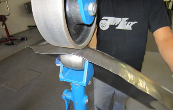
On the large upper wheel you can see it is covered with a rubber inner tube. This allows aggressive movement with such a tight radius. This also lowers the fatigue factor on your hands during wheeling because it does not take as long to shape a part. Note the grip gloves which also relaxes the hands a bit more during fab work. Oil is needed on the panels during planishing and bare hands and or standard leather gloves tend to slip.
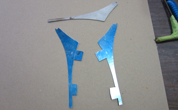
This is a really tight radius that goes in several directions. Although it is small in size it may be the hardest single part we will face on this custom bodied Camaro. In order to make it flow properly we did this mock up piece to see how well it will transition in to the tail light panel to satisfy the look I want. I need it to taper more gradual in to the panel yet still retain a thin outer edge. We will be building a convex shaped tail light panel so we will refine these sections afterward.
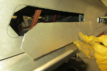
We pulled off the panels that were already fabbed as it is time to cut out the old tail light panel. We are going to stay with the original G.M. tail light design with billet frames to be shaped in accord with the new concaved shape tail light panel we will be building.
I made a final decision on the shape of the rear valance so we sliced some metal away to be sure that the profile flows with the back section we already have and it looks exactly the way I envisioned so lets do it. Measure twice cut once. Dishes are done and Diaper is gone, man.
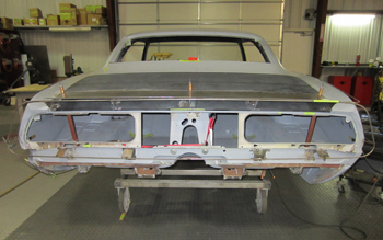
Out with the old and in with the new. Only the old factory tail panel bracing remains.
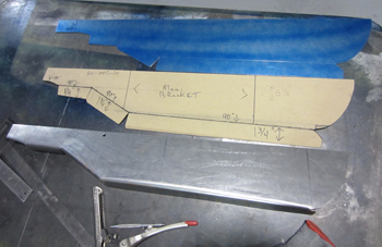
I had Mani shape up a quick rear valance to see how the lower qter would flow with it to determine the radius needed. As seen we have 4 different sections in place to see how they will all come together. Some tweaking is needed before we can build the full size panels so lets hop to it. We also laid out a chip board 69 Camaro factory sized tail light in place so\ we know our confines and then measured to build the tail panel full width.
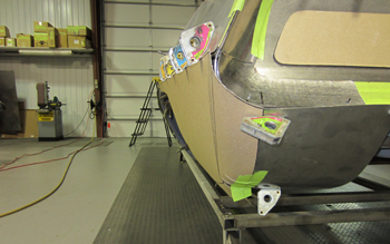
This view shows the side shot of the template we are considering. Overall I am happy with it so we can work on the lower qter.

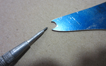
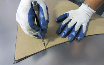
One of the techniques that Mani uses is to sharpie mark the metal with the template, then he uses a spring loaded center punch to leave small indention's on the surface so he knows where he is on the panel at all times. If he used the marker only it tends to get erased while working the panel in the english wheel and planishing hammer.
So we have a pretty good feel for all the panels and their respective shapes; We have tweaked the design to satisfy my eye and it is time to build it.
As seen our desired concave tail light panel will allow the upper spoiler and bumper to flow from one to another effortlessly which is my intent for maximum flow.
He lays out some 16 gauge for the tail light panel because after the tail light access holes are cut it will weaken the panel so the heavier gauge will make up for it.
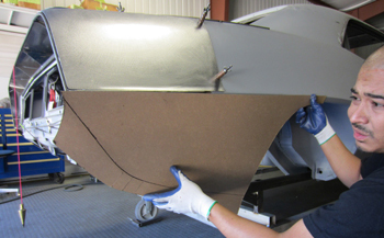
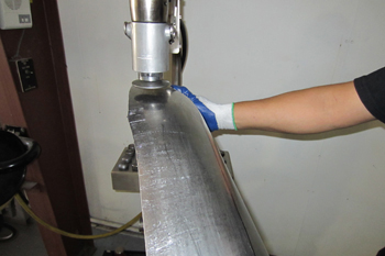
Mani wheels the big panel out as it takes shape in His hands.
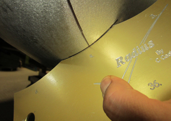
It matches our profile gauge so it is about ready to trim for placement.
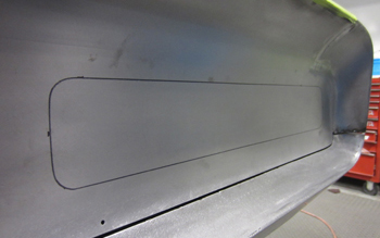
As seen we sharpie marked the area that also needs to be trimmed in order for us to install our new tail light panel. Once we get it all fitted we can remove the old factory qter sections.
Mani trimmed away some metal so we can fit the panel in. The reason we do not cut out all the back metal right now is to keep the unibody frame from stretching and or moving while we are fitting the wire forms.
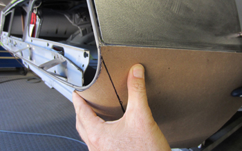
It is now in place and some trimming is needed to get it final fitted. When you get to this level you have to envision how it will all come together and your minds eye has to know that it knows that it knows that it will be sized symmetrically and flow together right when done.
As seen on the side she needs a little bit of trimming at the bottom.
We fit our right side qter chip board template to be sure the panels will not interfere with each other. We have clearance so its time to build the outer qter upper section.
We lay it out on 20 gauge and cut out the metal.
Mani fits it up to be sure it is what he wants.
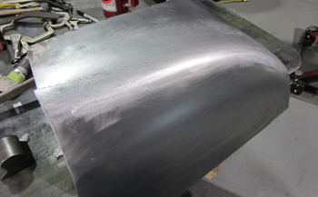
Some special wheeling will be done with the smaller lower wheels placed on the different sections.
You can see the radius starting to take shape.
The planishing hammer works it down a bit more.
Fits sweet, looks smooth and transition is " Dead On. "
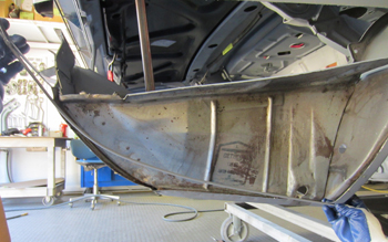
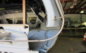
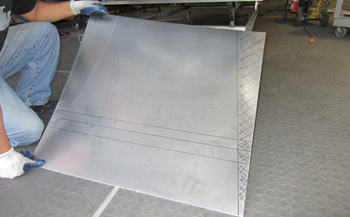
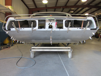
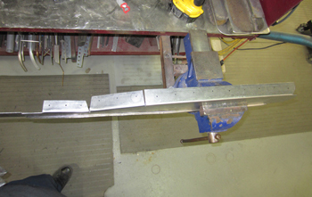
Ok, time to cut the old saggy shape away on the right side including the inner trunk drop off.. We matched the left and right side with our wire form and you can see the difference along side the old G.M design.
He holds the right lower qter template in place to check final fit and we are ready to proceed.
A close up shows the transition of the lower qter section and how it will go around the bumper. Sweeeet!
Lay it out on 20 gauge and lets get it knocked out.
He uses the spring loaded punch right through the template to mark the steel as discussed a few steps back.
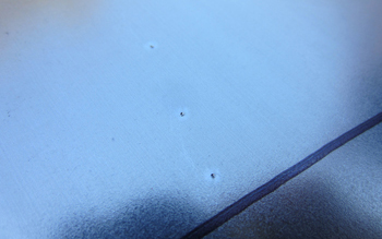
Close up shows the dimples left by the spring loaded punch, very easy to see while working the panel on the machines.

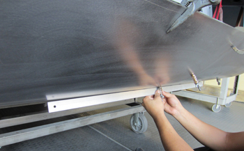
We use spray gun non silicone lubricant to eliminate any contamination problems in the shops.
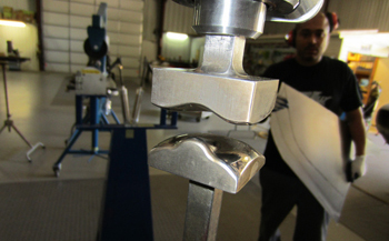
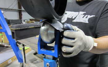
As seen the shrinking jaws on the pull max crimp the steel together thereby shrinking the steel to form the metal.
Marked and ready Mani places the steel in the machine to make a few passes.
He goes in to the second set of lines to achieve what he wants on this shape.
Notice the edge how it has rolled over and is taking shape.
A bit of wheeling and she comes around.
Planish the panel to smooth out the wrinkles. Lets fit it to see where we are at.
Cool, she is coming around but needs more tweaking.
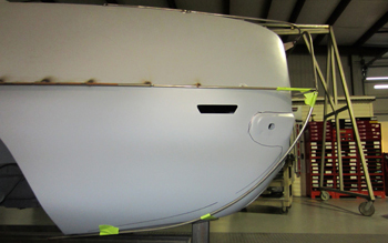
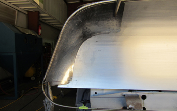
This angle shows the top to bottom transition.
The side view shows a new lower qter section in place. The wheel well edge will not be decided on until we get the wheels and tires under it.
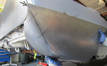
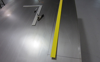
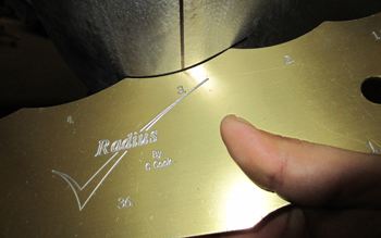
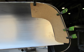
We marked the panel every 4 inches just to show the radius change so you can see the transition increments.
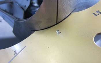
The top line shows a # 2 radius.
The next mark is a # 3 radius.
The lower mark is a # 4 radius. This shows how much it gets wider as it goes to the bottom a bit at a time. The smoother the taper or transition the prettier it is on any panel. I call it the " Flow Rate ".
Next we will fab the lower right valance section so we took our chip board template from the left side and simply flipped it over for an exact duplicate, then marked the steel and we are ready to start the process.
This is a subtle panel and pretty easy to make, we simply put a slight radius from the side to the center where we will join the left valance panel to it. In general the key is knowing what size to make the panels so there are the fewest pieces possible to minimize welding.
Mani fabbed the other side lower qter and valance panel and has it all clecoed together to check the fit.
Using a carbide scribe he marks the individual pieces so he knows where to cut/slice before final fitting.
He likes to use aviation snips to get the panel close to the silver scribe line then hand file it to a " Dead On " fit !
Panel to panel fitted she looks nice.
We are making sure that the valance has the convex shape we formed in to the left and right panels to an exact match side to side.
We remade the tail light panel end section a bit wider with more transitional flow in to the convex light panel. As seen it flows pretty nice.
Mockup for the right side is identical to the left side. We will show what was done to achieve our desired fit.
Shrinking the edge allows the part to fold over.
More often then not when they are really tight radiuses and or twisted like this part a shot bag and plastic mallet are needed to get the results we are looking for. A little wackage is in order !
A few whacks are needed to move steel. Usually around 8 to 12 inches away with normal pressure gets the job done, Son .
As seen she fits good. A little more tweaking.
Notice the high crown lower wheel for this part. She fits exactly like the left side so on to the next phase.
Time to go on to the bumper. We laid out chip board with the basic shape to match the mock up I designed and trimmed it to our liking. This is the top section only.
Next he laid the bumper out in 16 gauge steel because it needs to be stout. He took the " bad whammer " , which of course is our big nibbler that can cut through 1/4 inch steel and roughed it out. Time to refine and trim it a bit closer.
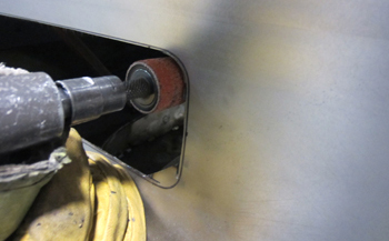
Using the dyna brade belt grinder he trims the bumper on the tight inside radius's to match the chip board and we are off and running.
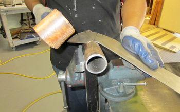
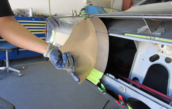
The leather covered mallet makes short work of it as He shapes it over a 2 inch pipe.
We like to pre-fit several times during trimming to be sure we are on spot. Notice the angle lines. Mani uses the wooden mallet with a leather wrap and a piece of round pipe to tweak it in to submission as 16 gauge is stubborn stuff.
Looking good.
Using duct bill vise grips he tweaks it in a weird angle to make the transition perfect. Note the individual angled lines as reference points.
I took the shark file and refined the bumpers edges to a straight line smooth surface. This way we will know where to trim the valance and tail light panel to achieve a 1/8th gap.
I actually bought out the MFG on these because they discontinued making them. They work great and come with rough and medium teeth.
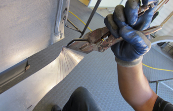
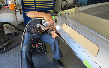
Mani fit the lower valance and the outer qter back in place and now he is wire tack welding every 1/2 inch using the Mark V torch. The joining of the two panels with a soft weld will allow him to wheel them together at the same time to refine any small imperfections before fully welding.

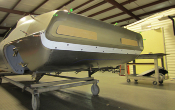
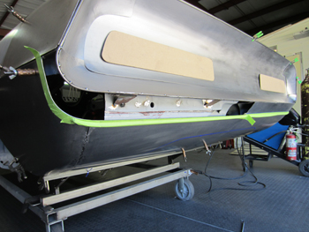
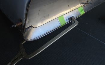
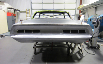
Tail light mock ups are in place and she is looking good.
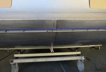
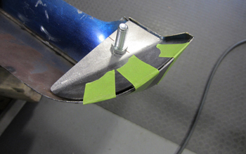
As seen I laid out some tape to get an idea of how I want the bottom bumper section to be shaped. Again my style is taping things and taking time to look it over and decide on the right shape before cutting. I also started taping off a design on the lower valance "see blue tape" where the exhaust panel will be.

Shaping the rear lower bumper section to flow in to the qter with a transition that is complimentary is a matter of taping it off, examining and changing it if its not right. This is pretty close.
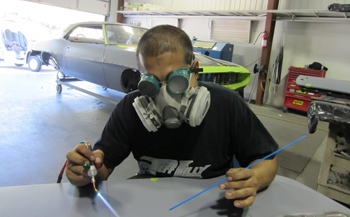
Using small magnets we make a template to fab the lower section of the bumper. The white transparent paper allows us to trace exactly on our dark blue vinyl tape.
A centerline is needed. This will assist in our side to side fit.
She is cut out and ready to build in metal.
We're all ready to slice and dice.
The bumper takes up a lot of space so a 4/8 sheet was needed.
We fabbed a wire from one side to the other that we tack welded to the panel for stabilization so we can cut out the excess valance panel metal to fit the new bumper. We also sharpie marked right on the blue tape lines edge then removed it and ran green masking tape on the out side of the sharpie line for protection where we will cut.
Mani cut it out and now we can fab the lower bumper.
As seen right on the line. Note the rounded edge of the bumper where it flows away from the qter at the top edge. As stated the "flow rate" is everything, the details make the difference.
On to the rear bumper brackets. He went to the box and pan brake and formed two ninety degree pieces.
He welded them in to the existing G.M. frame ends.
Now we have a place to mount the bumper for easy on off removal. Once we get the outer bumper sheet metal formed we will know how much depth to build the attaching brackets to mate the two together.
Bending the metal is pretty easy on an outside bend so no big deal as Mani trims and tweaks at the same time.
Twist and fit, twist and fit etc.
Grind a bit there and a bit here, you know the story, little by little.
She fits pretty good.
As seen the top of the bumper will require a cap as it is open. This will not be final welded until the bumper has been fitted and the brackets are built.
Template is in place.
Cut it in metal next and follow standard procedure.
Ready for placement.
Next we formed the brackets to attach the bumper where it will be bolted.
Mani used the tipping die to put a bend on the brackets. Heavy gauge steel needs heavy duty tooling.
Nice.
As seen we placed the spot weld holes to be drilled.
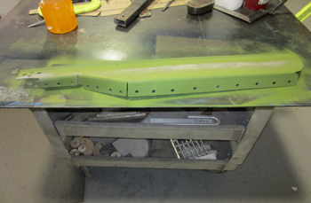
After drilling weld holes we applied aviation primer for hidden protection.
On the back side of the tail light panel we tack welded some tabs to the braces to keep it stable during fitting.
As seen the lip is just below the bumper. This will be welded to the bumper when we are ready.
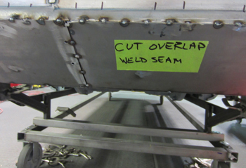
Now that we are sure that it will all line up we will weld the brackets to the bottom of the trunk floor.
We will also weld the center tabs as seen with the bumper removed.
We marked the bracket where all the welds will be placed.
Holes are drilled and ready to be welded.

Using self tapping screws we secured it in place and blasted the areas to be welded. Its party time.
He added a plate in the center to keep it all sturdy.
Clamp it in place, check fit, then weld.
Mani fabbed some brackets for the bumper to stabilize and locate the bolts for attachment.
Three per side should do the job.
The bumper end braces are a big help to make it behave during the welding process.
The metal is cut so we have them ready.
Fit and ready .
A bolt will be placed on each end to keep all the potential vibration movement away when the big cammed engine is running.
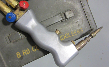
Our employee looks like an altered drag racer from the sixties with the gas weld apparatus on. Cool hand metal Luke.
We then get our wire forming Master in the mix to help get this bad boy done. We file the bottom edge of the bumper to fit to the valance.
Some 1/2 inch strap was used to stiffen the bumpers edge and provide a platform for body work if needed. They will be epoxied on with 3M panel adhesive to avoid any warpage.
Blast it and clean it up a bit.
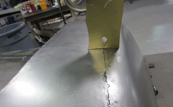
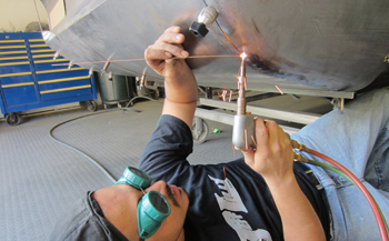
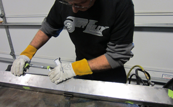
Mani welds the valance section together. Tack by tack careful by careful.
This bad boy welds some serious wire.
Tacked at first then hammer and dollied to keep shape.
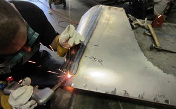
Time to fully weld them, perform a mild grinding then wheel them to perfect the smoothness of the panel.
The gas welding produces a soft weld which allows the weld to be easily smoothed by planishing and english wheel work.
It looks great and ready for attachment.
Time to blast the back side, prime and then permanently attach to the car.
White metal clean is the only way to go.
Moeler aviation green dries real quick. You can handle it in 10 minutes.
Weld in place time to rock.
It is also time to file a set of exact chip board templates to match our billet tail light trim so the holes we cut out in the tail light panel will be " Dead On ".
Qter panel cap offs are also needed.
Tacked in place for now until the end when we final inspect as they may need moving up or down.
Coming together
Attached with tape, centered, then marked for final cut.
OK here we go as Bob and i looked it over and feel this is the best positioning.
Well we did it. No turning back.
Round the corners to the line.
Fit the billet. Once we body work the tail light panel we will then file all the excess aluminum that hangs out past the edge for a totally smooth fit just like the theme of this build.
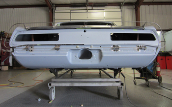
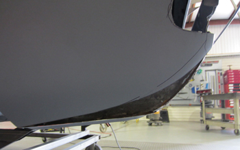
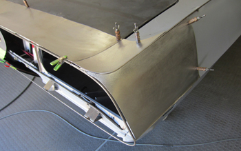
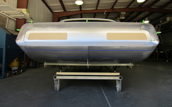
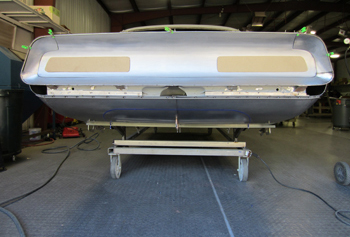
Although its not done it is coming along and about 85% finished before body and paint. The trunk lid still needs to be welded in solid along with the rear spoiler but it gives you an idea of what it will be once complete.
Looking good from the back side.